
Written by Pabs
So far, thoughts are to install 1 gauge for boost purposes, probably an Autometer Phantom as these match the Cupra’s dash lighting and style the most. Rough price for pod is £44 and gauge is £34 inc p&p if you import from the USA, or £66.70 in the UK, from Apex Performance. (You can guess which option I took cant you?) The single A pillar pod came from Nomad Racing for £50.50 including delivery, and a full fitting kit. At this point i would just like to thank Vanessa at Nomad for BEYOND EXCELLENT service – the part wasn’t in stock at time of order, and so i didn’t have to pay delivery. The part was with my well within a week from ordering anyway! So THANKS to Vanessa and ALL at Nomad Racing!
|
Part Numbers Required
|
Description
|
Approximate Prices (exc VAT)
|
|
#5703
|
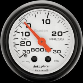
Autometer phantom 30psi boost/vac gauge
|
£51.50
|
|
N/A
|
Plastic T Piece and 3mm tubing
|
£0.7
|
|
N/A
|
Scotch lock connectors x 2
|
£0.3
|
|
N/A
|
Cable Ties x5
|
£0.5
|
- Autometer Phantom 30psi boost/vac gauge, #5703
-
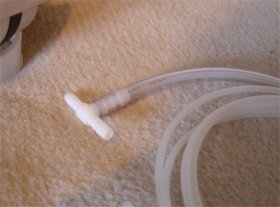
There are a few install guides available on the internet, one being from fellow SCN member RobDon. See his site here for more info. The autometer gauges do not come with a T-piece to join into the DV pipework, or the little silicon hose that will join the t-piece to the gauge hose. These parts can be obtained from B&Q or DIY places, and cost very little. The picture below should show the components that I am referring to.
T-piece inserted into 3mm silicon tube, with gauge hose running through the hose into the t-piece.
-
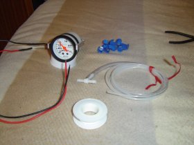
Parts required (from left) Gauge, two lengths of wire, scotch clamps, t piece, 5mm hose, gauge hose, ptfe tape.
Step 1
The first move is to extend the wires on the gauge bulb, as they are probably not long enough to go from the gauge to the power source in the dash. I did this using a soldering iron and heat shrink. Also, I put the red rubber boot on the lamp so that the illumination of the gauge matches the interior illumination in my car.
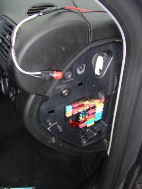
In your car, remove the fuse box cover (lid) and then undo about 7 or 8 torx screws so that u can remove the plastic part that holds the fuse box in place. This gives you access through to the illumination control which you will need later, and also possibly finding the boost gauge hose….. which is gonna be used in step 2!
-
Step 2
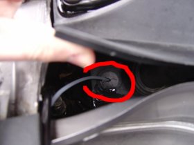
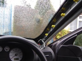
I decided to try to route the hose from the engine bay through to the gauge location next. This is actually quite tricky, regardless of what others say…. In the engine bay, underneath the windscreen wipers there is a plastic cover. Under here, you will see where the bonnet release cable goes into the cabin. Just up, and to the right of this, there is the main cabling grommet, which has two unused grommets, one either side. Using a HAND DRILL (so as not to cut any wires behind) drill a hole large enough to thread the boost hose through and into the cabin. When this is done, you can try to thread the hose through into the cabin. However, I found this very hard, as I couldn’t see where it was coming in from. Alternatively, you can remove the whole of the bottom dash by removing all the torx screws under the fuse box cover, and then you will find 3 torx screws underneath the steering wheel which need to be removed.
Grommet to route the hose into the cabin – in the picture there is no sealant, but to be safe its best to use silicon or similar to stop water ingress
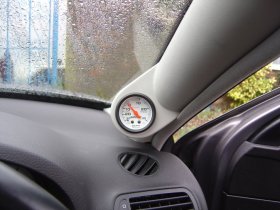
- Trial Fitting to see what it will look like.
-
Step 3
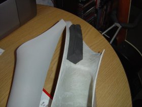
Remove the old A pillar. This is a case of pulling hard on it towards the passenger side of the car until it un-clips. It does sound like it is gonna snap, but it wont….. Eventually it comes off.
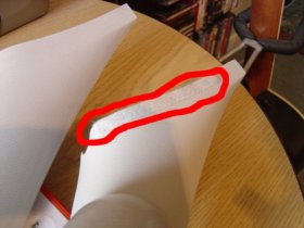
- Now, transfer all padding from the old a pillar to the new one, as shown in the two pictures below. This is the large grey block towards the bottom of the pillar, and the small fabric strip on the leading edge.
- This is the front protective strip – also there for a reason 😛
-
Step 4
Now is time to wire the bulb up. Remove the bulb, holder and cables from the gauge. Something I haven’t done yet, but will do, is change the bulb for a brighter, red one. The standard one and red cap (shown in a picture below) gives off a rather dull “orangey” glow, rather than the red I expected. www.autobulbs.com supply these apparently.
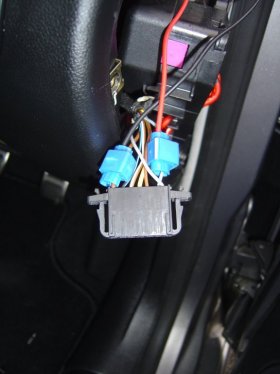
Remove the side of the dash that covers the fuse box. From here, undo approximately 8 torx screws until the plastic side panel comes off, and the fuse box is free to move. Behind the light switch and dimmer control is a long plastic connector. Squeeze the top and bottom catches together and pull it out. From here, I then used two scotch locks to connect the wires to the bulb. The far left is a brown wire. This is the GROUND connection for the bulb. The 2nd cable from the right (white/blue I THINK) is the dimmer wire, so connect the +ve connection here. Your wiring should now look like shown.
Far left wire (brown) is the ground connection, 2nd cable from the right is the dimming connection
- Now, run the cable for the bulb up through the A pillar hole, and replace all connectors and cabling before putting the side of the dash back together. Put the cover back over the side, and that’s the wiring done 😛
-
Step 5
Right, now its time to get the gauge into the pillar, and secure this to the car, using the Velcro strips that come supplied with the nomad pillar. Firstly, put the gauge into the hole, and using the Y bracket and nuts, tighten it in the right position. I think my pillar is slightly wrong as I couldn’t get the gauge perfectly flush due to the y bracket fouling up on the inside of the pillar. Nevertheless, it fitted tightly enough so I wasn’t too worried. (For now, at least) Following the instructions for the gauge, and MAKE SURE you use PTFE tape on all of the threads, attach the hose to the gauge itself. Make sure the bulb is back in the gauge, and then attach the Velcro to the a pillar and vehicle. This Velcro is actually fairly strong, and so nothing else was needed for mine, although my Velcro wasn’t positioned as well as it could be. A little more planning here would help…..
Now check your back light by turning on your sidelights, and mess around with the illumination dimmer until you are happy its working!
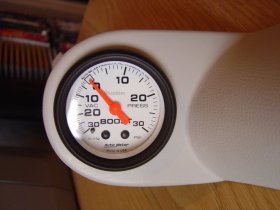
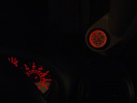
- Boost gauge at night, with the standard bulb illumination, but intensity of dimmer is quite high.
-
Step 6
The final step for me was to attach the hose to the car engine. Being a total novice, this was actually quite scary :S
After numerous conversations with members of SCN, I decided that the best place for me to route my hose to was the top of the DV. The hose only just reached and it needs to be tied to some points to stop it from getting too close to the engine. I secured my hose to my t-piece by means of cable-tie. This was tight enough, and I didn’t want to use jubilee clips in fear of crushing the t-piece or hose.
Cut the hose going to the DV. Put the t-piece in, and cable-tie the hoses to the t-piece, nice and tightly. Your hoses should now look something like this:
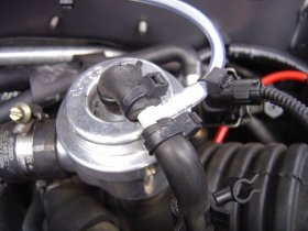
That’s it! Get in the car, and turn on the engine. The first thing you should notice is that your gauge gives a negative boost (VAC – if your gauge has this on display, as some only show +ve boost) My readings dropped to -20PSI. Revving the engine should make the needle go to around 0PSI, and when the car is accelerating it can read a peak of anything between 8 and 12PSI, and it should hold around 6-9PSI. Different cars have different readings, but if yours isn’t anywhere near these then there is something wrong. Check for leaks and kinks in the hoses, and make sure nothing has popped off.