Seat reverse camer badge
- Thread starter p11lkw
- Start date
You are using an out of date browser. It may not display this or other websites correctly.
You should upgrade or use an alternative browser.
You should upgrade or use an alternative browser.
That looks mint but im not clued up with rc/servos. I love how complicated it looks but i bet it was enjoyable to do. Well done again! Truly awesome
Step by step guide
Ok this is for people who are interested in having ago at fitted a reverse camera into the boot badge. This might take a while and I will try my best with this guide.
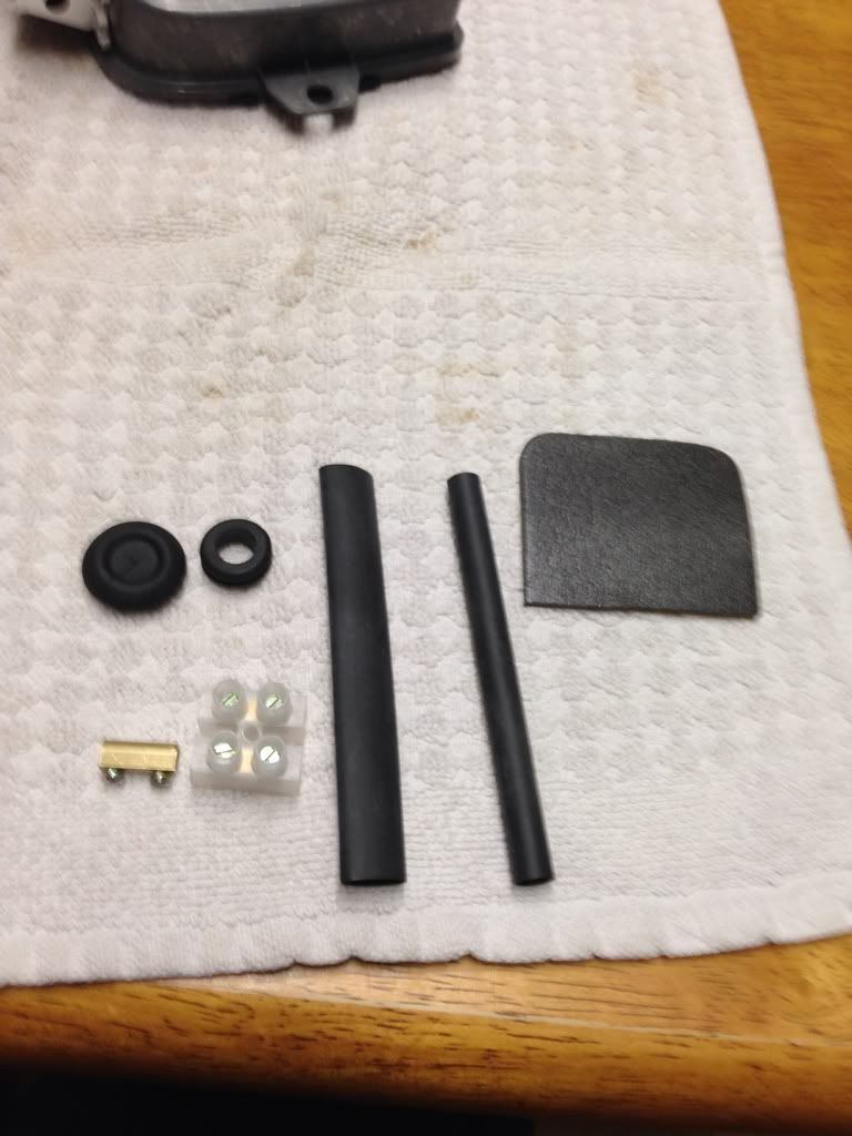
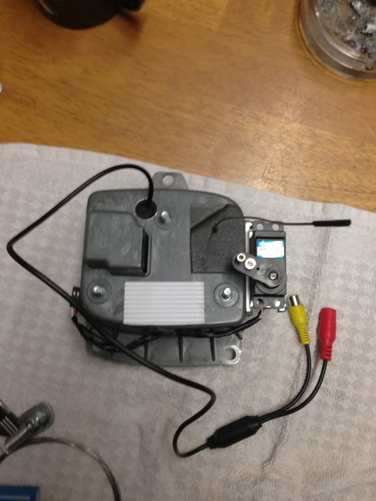
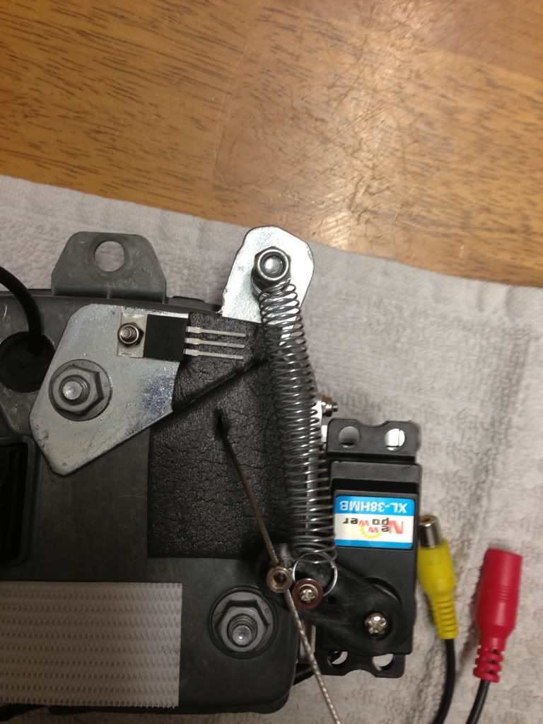
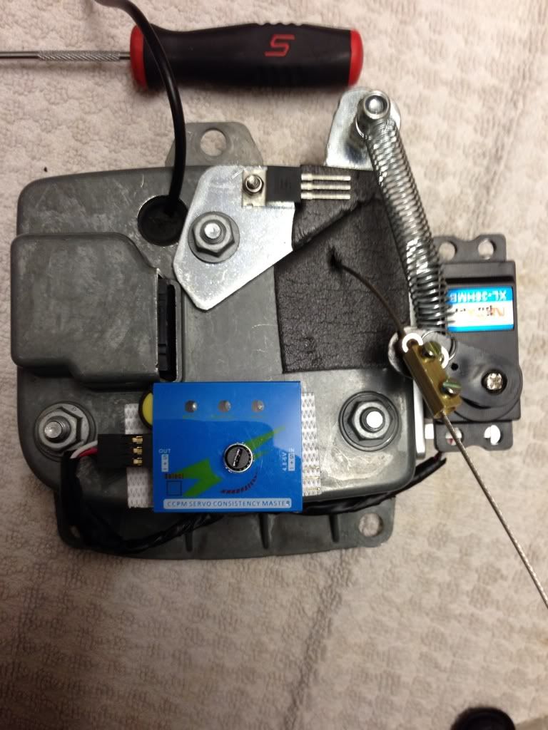
Firstly a few pictures of some of the parts used.
Bike inner gear cable, servo driver/test, bracket I made with spring and 12v-5v voltage reducer.
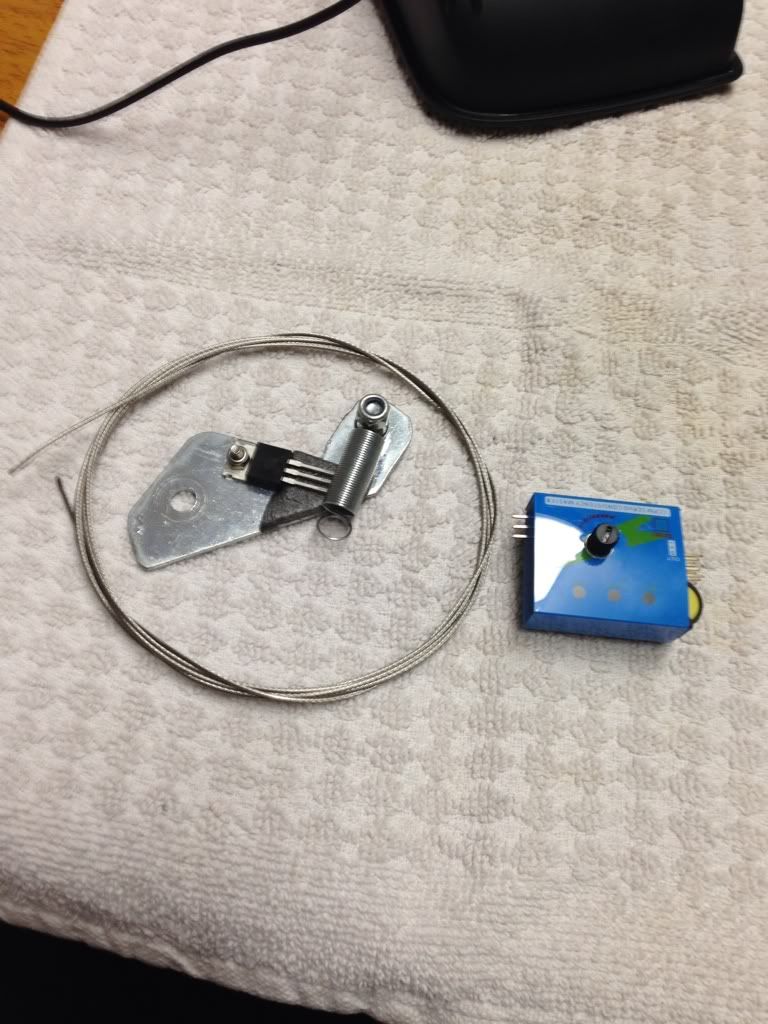
Rubber seals, electrical connector block which I've taken the plastic off, heat shrink
Ok this is for people who are interested in having ago at fitted a reverse camera into the boot badge. This might take a while and I will try my best with this guide.
Firstly a few pictures of some of the parts used.
Bike inner gear cable, servo driver/test, bracket I made with spring and 12v-5v voltage reducer.
Rubber seals, electrical connector block which I've taken the plastic off, heat shrink
Just a thought.. This might be a pre FL mod only as I'm sure the boot badge is smaller on the FL's or is that just my imagination?
Haha your probably right!
ordered myself a camera today anyway, for £10
if its crap, im sending back!!!
Anyone know if this will work with RNS 315 and RNS310 as this is what most leons have IIRC
Got an AUX input on back of unit?
Step by step guide
Incase people are not sure how to get at the back off the boot badge here goes.
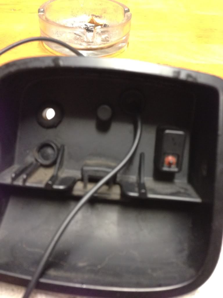
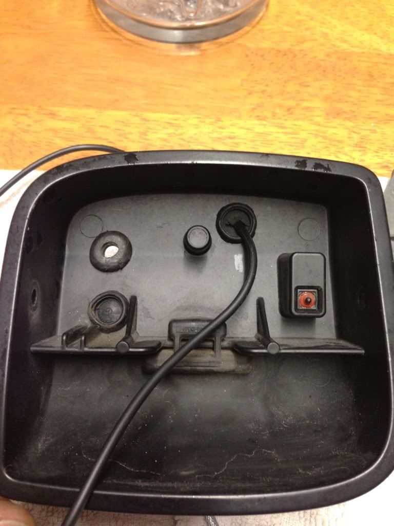
Open the boot and you will see the black (in my case black) plastic cover attached to the boot lid. There are 2 screws, 1 in each side where you grab to close the boot, once removed the cover will unclip with a firm pull no need for trim tools on this one.
Unclip the wiring from back of the boot badge then remove 6 10mm nuts and remove the boot badge 1 half from inside and the other from the outside. Easy that bit.
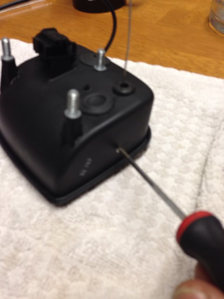
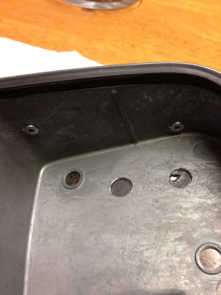
Now we need to split the badge half again. First with a small punch or screwdriver you need to push out the pin like so, might require a bit of force but it does come out but only one way, look closely at the pictures if not sure.
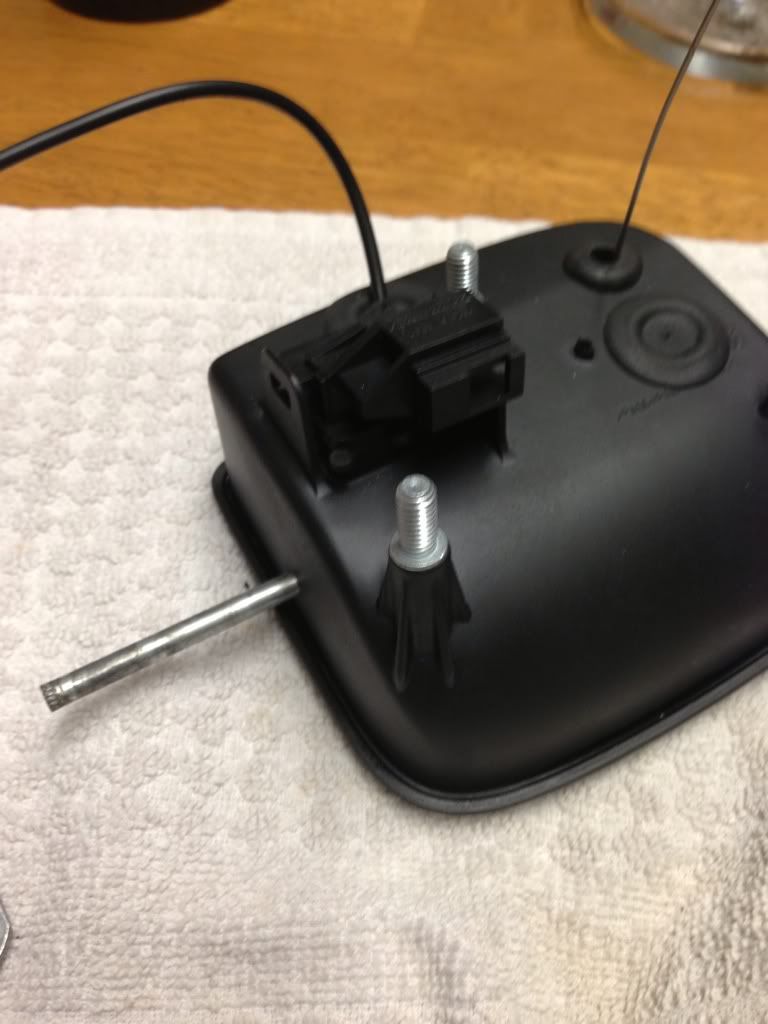
Ok so now you've separated it here come the hard/tricky part. You need to seperate/remove the chrome seat badge being careful not to brake it, tools you want to use if you have them
Plastic trim tools small screwdrivers. Prise off a little at a time working around one end.
You can just see in the picture how its clipped on ignore the cable that I've fitted for now I will get to that.
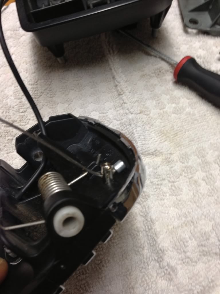
Once seperated you have a good look how the badge is fitted so you see where you might have enough room for a small rod eyelet to bolt through which won't effect the seat badge being clipped back on. I bolted mine on just above the spring.
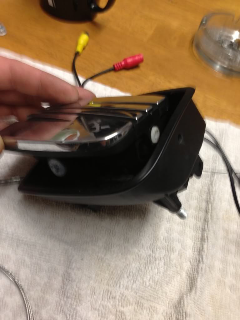
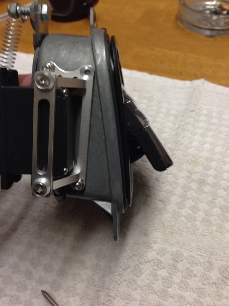
Now to mount the camera, I cut a slot in the plastic just big enough to slide the camera cable in. Then offer the camera in place as close to the slot you've just cut. This is because you will need as much Clearence as possible also the butterfly bracket on the camera needs to be bent as close to the camera as possible. Once the camera is in the position you want mark and drill pilot holes, then using 2 small counter sunk bolts bolt the camera in place so that they are counter sunk which will not effect the badge being clipped back on which you can now do. Thread the gear cable through the rod eyelet see pictures.
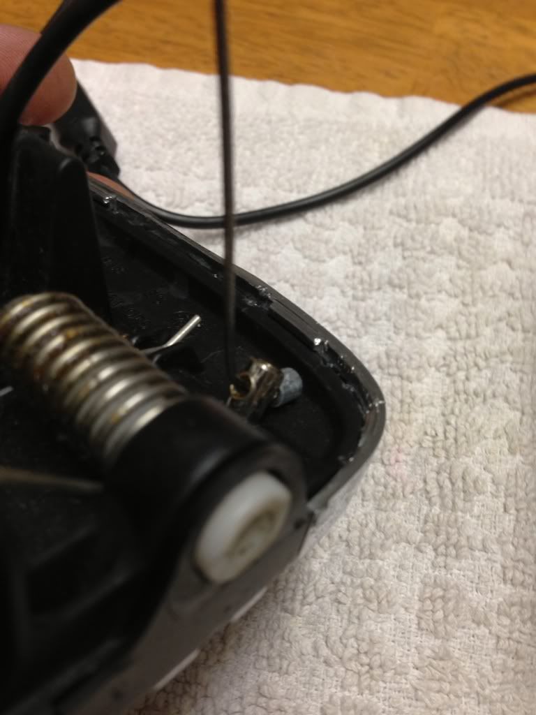
Next is to drill holes through the plastic backing and the metal part. 1 for the gear cable and 1 for camera wire. Make sure you have some good drill bits and don't force them, nice and steady letting the drill bit do the work slowly.
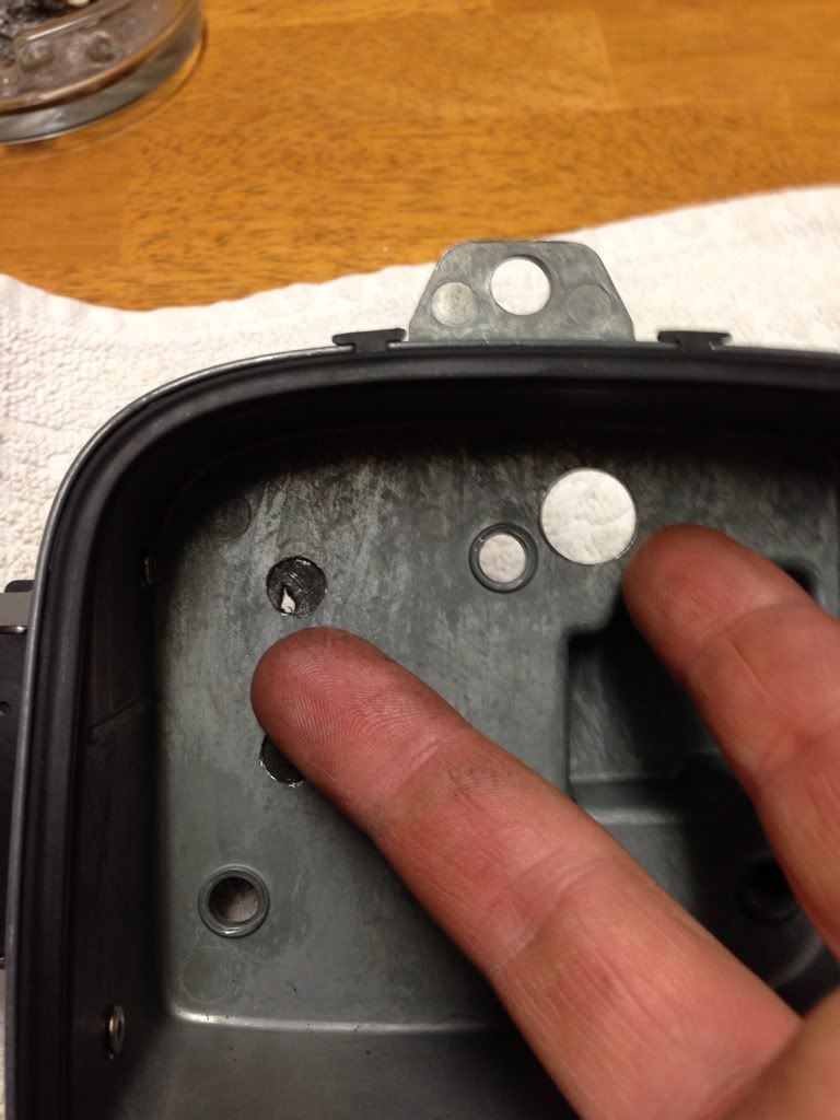
The holes need to be big enough for the rubber seals your going to use and for the camera wires to fit through.
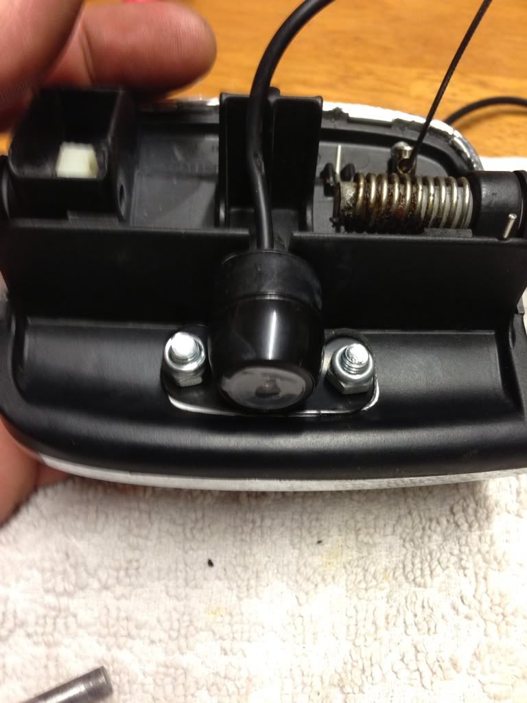
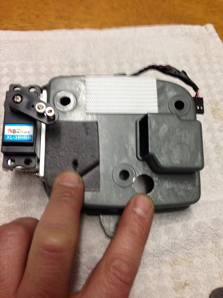
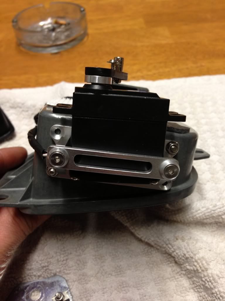
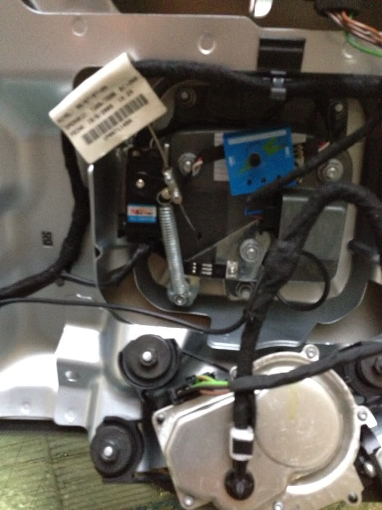
Next is to mount the servo clamp using the counter sunk bolts that came with it. I only used 2 of these because the less holes the better so water has less chance of coming in and 2 is enough. These need to be counter sunk otherwise the badge part won't fit back in.
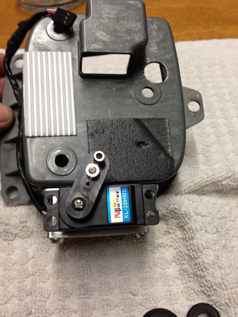
Now start putting everything back together so you can see how it will all work and to finish the rest.
Next is to make a bracket with a bolt in for the spring some like this. I mounted the voltage reducer to this as well.
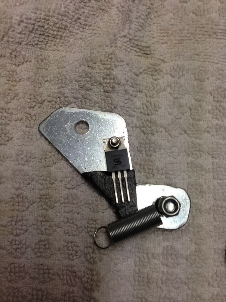
Using the existing bolt/nut to mount it.
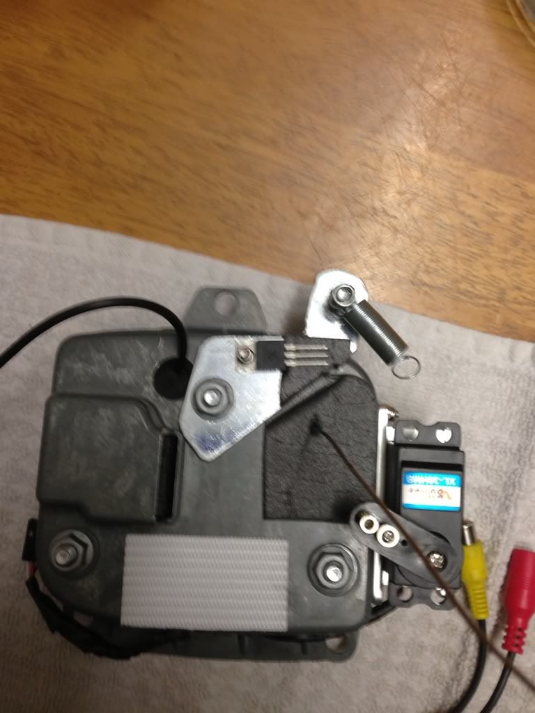
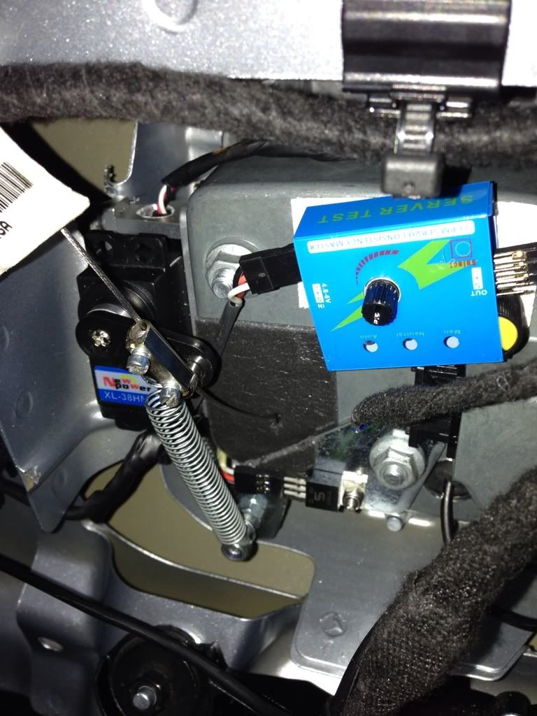
Attach another rod eyelet to the servo arm and thread the gear cable through and using just the metal part of an electrical connector slide down the cable. This is now your adjuster set this with this with the badge open by pulling the cable so it doesn't operate the micro switch then tighten the electrical screws. Note this is trial and error as the arm and servo need to be in the correct position for this to work properly. I mounted the servo driver/tester on the back of the boot badge with Velcro. Plug the servo into the servo tester. At this point I made a demo wiring loom connected to some batteries 4 aa batteries 6v so I could bench test it to set up the servo and servo arm. Once I figured out how it was all working and set it up correctly I attached the spring to the servo arm.
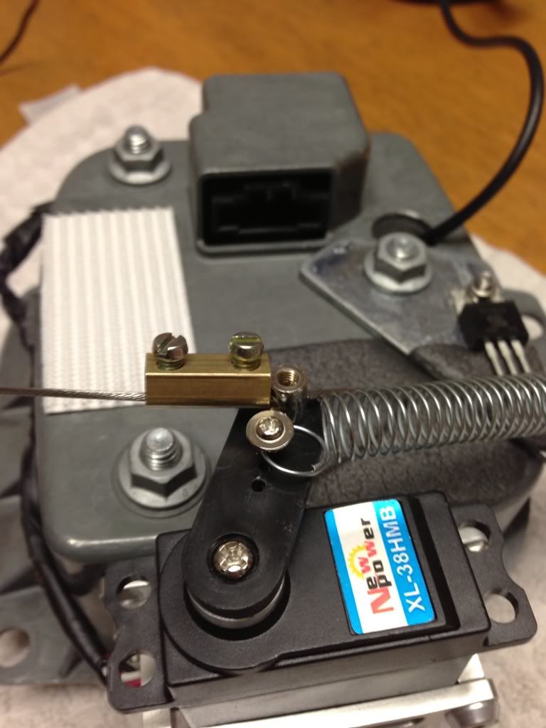
How it works: power on servo arm opens pulls the cable and opens the badge power off the spring will pull the servo arm back and close the the badge shut. This is provided your using the correct spring (length and strength) now it's all working seperate and fit to the car boot. Unfortunately you will have to set the cable attached to the servo arm again.
You will need to make your own wiring loom. 12v Positive and negative for the reverse light going into the voltage reducer 5v positive coming out going to the servo driver/tester as well as a negative. You should be good to go. Now test by selecting reverse gear etc. now run the camera wire to HU one which is compatible with a reverse camera. I have a RNS 510 and I've had to purchase a separate av camera interface. The camera will also take its Power from the reverse light.
http://i1288.photobucket.com/albums...684700-17980-000009DD57EC8C03_zps7bd89a06.mp4
I hope people can understand all this. Feel free to ask questions if you don't and I will try and help. If you are unsure about attempting any wiring the please see an auto electrician.
Should anything go wrong I won't accept responsibility. It's your own risk.
Incase people are not sure how to get at the back off the boot badge here goes.
Open the boot and you will see the black (in my case black) plastic cover attached to the boot lid. There are 2 screws, 1 in each side where you grab to close the boot, once removed the cover will unclip with a firm pull no need for trim tools on this one.
Unclip the wiring from back of the boot badge then remove 6 10mm nuts and remove the boot badge 1 half from inside and the other from the outside. Easy that bit.
Now we need to split the badge half again. First with a small punch or screwdriver you need to push out the pin like so, might require a bit of force but it does come out but only one way, look closely at the pictures if not sure.
Ok so now you've separated it here come the hard/tricky part. You need to seperate/remove the chrome seat badge being careful not to brake it, tools you want to use if you have them
Plastic trim tools small screwdrivers. Prise off a little at a time working around one end.
You can just see in the picture how its clipped on ignore the cable that I've fitted for now I will get to that.
Once seperated you have a good look how the badge is fitted so you see where you might have enough room for a small rod eyelet to bolt through which won't effect the seat badge being clipped back on. I bolted mine on just above the spring.
Now to mount the camera, I cut a slot in the plastic just big enough to slide the camera cable in. Then offer the camera in place as close to the slot you've just cut. This is because you will need as much Clearence as possible also the butterfly bracket on the camera needs to be bent as close to the camera as possible. Once the camera is in the position you want mark and drill pilot holes, then using 2 small counter sunk bolts bolt the camera in place so that they are counter sunk which will not effect the badge being clipped back on which you can now do. Thread the gear cable through the rod eyelet see pictures.
Next is to drill holes through the plastic backing and the metal part. 1 for the gear cable and 1 for camera wire. Make sure you have some good drill bits and don't force them, nice and steady letting the drill bit do the work slowly.
The holes need to be big enough for the rubber seals your going to use and for the camera wires to fit through.
Next is to mount the servo clamp using the counter sunk bolts that came with it. I only used 2 of these because the less holes the better so water has less chance of coming in and 2 is enough. These need to be counter sunk otherwise the badge part won't fit back in.
Now start putting everything back together so you can see how it will all work and to finish the rest.
Next is to make a bracket with a bolt in for the spring some like this. I mounted the voltage reducer to this as well.
Using the existing bolt/nut to mount it.
Attach another rod eyelet to the servo arm and thread the gear cable through and using just the metal part of an electrical connector slide down the cable. This is now your adjuster set this with this with the badge open by pulling the cable so it doesn't operate the micro switch then tighten the electrical screws. Note this is trial and error as the arm and servo need to be in the correct position for this to work properly. I mounted the servo driver/tester on the back of the boot badge with Velcro. Plug the servo into the servo tester. At this point I made a demo wiring loom connected to some batteries 4 aa batteries 6v so I could bench test it to set up the servo and servo arm. Once I figured out how it was all working and set it up correctly I attached the spring to the servo arm.
How it works: power on servo arm opens pulls the cable and opens the badge power off the spring will pull the servo arm back and close the the badge shut. This is provided your using the correct spring (length and strength) now it's all working seperate and fit to the car boot. Unfortunately you will have to set the cable attached to the servo arm again.
You will need to make your own wiring loom. 12v Positive and negative for the reverse light going into the voltage reducer 5v positive coming out going to the servo driver/tester as well as a negative. You should be good to go. Now test by selecting reverse gear etc. now run the camera wire to HU one which is compatible with a reverse camera. I have a RNS 510 and I've had to purchase a separate av camera interface. The camera will also take its Power from the reverse light.
http://i1288.photobucket.com/albums...684700-17980-000009DD57EC8C03_zps7bd89a06.mp4
I hope people can understand all this. Feel free to ask questions if you don't and I will try and help. If you are unsure about attempting any wiring the please see an auto electrician.
Should anything go wrong I won't accept responsibility. It's your own risk.
If I had a RNS510 Id be all over it 100%
Doesn't have to be an RNS 510! What HU have you got ?
Doesn't have to be an RNS 510! What HU have you got ?
...or anything with a screen
")
I just have the plain RDS 310.
Doesn't even stream Bluetooth. Does my head in!!
...or anything with a screen
I just have the plain RDS 310.
Doesn't even stream Bluetooth. Does my head in!!
Mmm new HU required then unless you opt for a small monitor
Great work man, thats amazing.. i wouldnt mind having a go at this, but first need to get my RNS510, will be keeping an eye on this thread
Similar threads
- Replies
- 2
- Views
- 2K