PCV removal - can this be done? YES! removed + catch tank fitted

MJ

Public transport abuser
Apr 22, 2008
5,508
13
Manchester
m.facebook.com
Thanks for posting mate, was planning on sending you a PM. I'd seen you were pro the modification in a thread on the ibiza section. The catch tank I've ordered off eBay is not baffled (would post the eBay link but cant get to it whilst at work).

Use metal scowering pads and a pair of tights as oppose to baffles.
 

csd_19

Full Member
May 11, 2005
2,272
17
Angus / Edinburgh
I wouldn't remove that brake booster section like the guy on the mkiv forums has...

The section of pipe he removed was connected through the PCV system and the vacuum drawing on it was produced from the TIP, hence there was always a source of vac on that line, whether at idle or under acceleration. And since there is always a source of vac pulling on that line, there is no chance an oil vapour, sludge, gunk etc can get into that part of the lines...


He's left the connection at the manifold and this will only be drawing a vacuum when either idling or under deceleration - the one-way valve prevents boost pressure destroying the vacuum.

I'd personally leave both hoses connected on the brake booster system :)

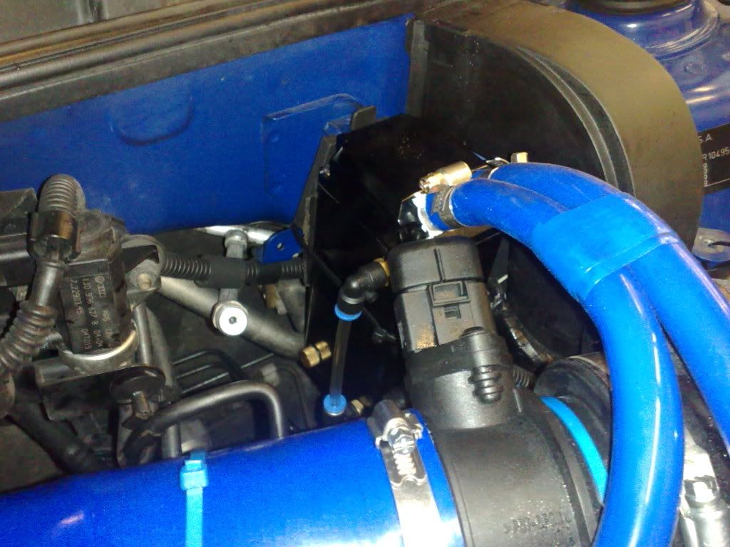
I run a catch can on mine and it is hooked back into the TIP to maintain the vacuum and help scavenge from the crankcase.
 
Nov 29, 2007
736
0
Mansfield, Notts
if you look at the way he has installed the catch can it does feed back into the TIP. The crankcase is T'd in the cam cover before the catch can. The second pipe goes straight to the TIP (via the black mushroom DV looking thing). So under load the draw will be created by the pipe to the TIP.

If you attempt to break whilst accelerating or driving the ECU then ignores the input from the throttle pedal... this must then force the inlet manifold to create a vacuum?

But I will defo double check every thing and make sure I've got all the bases covered before I do the mod and test drive.
 

csd_19

Full Member
May 11, 2005
2,272
17
Angus / Edinburgh
if you look at the way he has installed the catch can it does feed back into the TIP. The crankcase is T'd in the cam cover before the catch can. The second pipe goes straight to the TIP (via the black mushroom DV looking thing). So under load the draw will be created by the pipe to the TIP.

If you attempt to break whilst accelerating or driving the ECU then ignores the input from the throttle pedal... this must then force the inlet manifold to create a vacuum?

But I will defo double check every thing and make sure I've got all the bases covered before I do the mod and test drive.

Yep nowt wrong with the catch can installation there :)

I'm guessing that the brake system was designed with two vac lines in case one failed somehow? Or to provide a stronger vac? :confused:
 
Nov 29, 2007
736
0
Mansfield, Notts
Yep nowt wrong with the catch can installation there :)

I'm guessing that the brake system was designed with two vac lines in case one failed somehow? Or to provide a stronger vac? :confused:

I'm not sure how the OEM piping works if there is a leak. If there are no leaks then I can only assume that the two pipes are creating vacuum. But if you have a leaky pipe or pipes like myself a vacuum can not be created because ther is no air tight seal.

So weather you have one or two pipes connected, once one fails the other will surely either not work or be really weak?
 

csd_19

Full Member
May 11, 2005
2,272
17
Angus / Edinburgh
I'm not sure how the OEM piping works if there is a leak. If there are no leaks then I can only assume that the two pipes are creating vacuum. But if you have a leaky pipe or pipes like myself a vacuum can not be created because ther is no air tight seal.

So weather you have one or two pipes connected, once one fails the other will surely either not work or be really weak?

It'd depend where the leak occurred I assume, i.e. upstream or downstream of a check valve etc.

Are you thinking of replacing everything under the mani (suction jet etc etc) or just looking to replace the split hoses and add a catch can?

Either way, hope the mod turns out well Jason, remember to get photos up of the latest shiny bits! :D;)
 
Nov 29, 2007
736
0
Mansfield, Notts
I'll be removing everything I recon. The suction will be created by the draw from the TIP. I'll take a few photos and post in this thread once the mod is complete.

Everything is either on order or available at the local spares place; its just down to when Parcel Force and Royal Mail registered post get round to delivering it. If it comes this week I have it done ASAP... the wife wants her car back!
 
Nov 29, 2007
736
0
Mansfield, Notts
Catch tank arrived today by Parcel Force and I ordered it Sunday night. :-o :clap:
1yrgyg.jpg
 

MJ

Public transport abuser
Apr 22, 2008
5,508
13
Manchester
m.facebook.com
No pics as of yet but i fitted it where the black relay box is near the maf sensor, it comes to bits very easy and you can remove the relays and move them out of the way, i also cut the bracket off the plastic box and used it to mount the tank.
 
Nov 29, 2007
736
0
Mansfield, Notts
PCV removed - Catch tank now fitted...

I removed the PCV system last weekend and fitted the catch tank. It took me most of saturday and I finished it off sunday afternoon. I took my time and didn't force any thing, but now I've done the mod I think I could do it in half the time.

I wanted to run the car for a week before giving my views... the car has never run so smooth since I've owned it (2 years now). the tickover is spot on with no jumping, the lumpy acceration has gone, the car feels alot stronger through the rev range and strangly I'm sure the brake pedal has got firmer.

Just goes to show that a totally knacked Y breater and PCV system can trash the cars performance.

Some pic's:
1yvhxw.jpg


1yvhx0.jpg


1yvhxz.jpg
 
Nov 29, 2007
736
0
Mansfield, Notts
The tank was off eBay and £30 inclusive of p+p and its made by Toyosports. All the hoses came from the local car spares place. I'm not hundred percent on the 4mm and 8mm pipe sizes as I cut bits off the old pipes and took them with me.

I think the little vacumn pipe under the maifold was 4mm; once the PCV is removed there are two outlets under the manifold that are not needed so I've looped those with 8mm pipe.

The main pipe should be 19mm but they only had 3/4 inch - but once warmed up in a cup of boiled water they soften up. These are sleved over 1/4 inch on the catch tank its self. The outlets are supposed to be 15mm but were actually 12-13mm. Did the same thine there - took the top off the catch tank and soften up two small bits and put them on the outlets. Once cooled sleeved with the 3/4 inch. there is no way they are coming apart.

The hardest part to find was the T-peice, could not find one and was about to give up when I tried the local garage where the wife's car goes to ask if he knew somewhere... he went out the back and pulled one straight out of a bag with loads in and charged me £2.
 
Last edited:
Nov 29, 2007
736
0
Mansfield, Notts
You did well to get that in there mate... I looked there but couldn't work out how I was gonna get it to fit, I ended up thinking that my set-up in that area was slightly different out of the factory - but it ain't I just couldn't sort it out.

Gonna swap mine out for silicon in the summer I think.
 

mrwookie

Big Daddy...
Mar 22, 2008
716
0
Cambs & Herts
Its the round black plastic valve that looks like a mushroom and is located on the right hand side of the engine and connects via a breather pipe to the top of the block.