Hello fellow enthusiasts!
As this is my first post on the forums, I'm going to talk about one of the first things I did when I purchased my Mk1 Leon Cupra R. There are so many indecisive guides and threads out there that either provide the wrong information, or haven't got enough info to actually understand how to install a Catch Can and the best way of doing so. I've looked on VWVortex, SeatCupra, AudiSport and plenty of other forums to decipher the correct way of doing it.
I haven't been here long, but I have used these forums so much recently to diagnose and fix problems with my motor, so I think it's time for me to give back.
There are many ways to install a oil catch can, many different types and also pros and cons of each. In this particular thread I'm going to talk about removing the original PCV system, and simplifying it with a Catch Can.
Let's first talk terminology;
'OEM' - Original Equipment Manufacturer
Self explanatory - the original piece of equipment or item provided at point of sale or purchase of car.
'PCV' - Positive Crankcase Ventilation.
Some may refer to a 'PCV Valve', however the PCV is a system comprised of many valves and pipes.
The PCV system as a whole removes gases such as unburnt fuel and oil vapors from the engines crankcase and on stock / oem systems will normally cycle the vapors back into the TIP to be re-burnt in the engine.
'Hockey Puck Accumulator Valve' - I'm not exactly sure the exact name of this part, however most people refer to it as a hockey puck due to the shape.
The hockey puck is supposed to help filter out the oil mist in the vapors that come out of the CBV and VCB before sending the rest to the TIP.
The hockey puck will also help to bleed air through during heavy vacuum.
'TIP' - Turbo Intake Pipe
This is the tube that runs from the airbox into the turbo)
'Catch Can'
This collects the unwanted oil and fuel vapors in the feed air via a set of baffles, accumulates the oily liquid and then returns cleaner air to the TIP or in some cases - vented to atmosphere. (This depends on the catch can you have purchased. I would advise a return to TIP as these don't spew oil, and will still pass MOT's. I will talk more about this later.
'CBV' - Crankcase Breather Valve
This is a 90 degree pipe that is located near the bottom of the crankcase which will vent some of the unwanted gases.
'VCB' - Valve Cover Breather
This is located at the top of the engine on the side, it's a small pipe that sticks out of the valve cover that will vent some of the unwanted gases.
Types of Catch Can
All catch cans do the same thing. They take away unwanted gases from the crankcase and valve cover and separate the oil and fuel from the air and will accumulate in the can/tank.
There are different options when considering a catch can;
1) Standard Catch Can - These just simplify the PCV system, the catch can will collect vapors, separate the oil/fuel mix and recirculate the clean air into the TIP.
2) Vent to Atmosphere - As it sounds, this will vent unwanted gases straight to the atmosphere instead of recirculating back into the TIP or accumulating in a tank.
3) Oil to Sump - These catch cans send the oil/fuel mix back into the sump where the oil is then recycled into the engine.
To learn more about the different types of catch cans, please watch the following YouTube video to decide which one is right for your needs -
I personally would recommend a standard catch can, that accumulates oil and vents the clean air back into the TIP. You can purchase the one I have from Creations Motorsport here:

 creationsmotorsport.com
Installing a Catch Can on my 1.8T LCR 225hp (It is the same principle for all engines out there, but things may look different and be in different places)
Anything that I say that will be on one side of the engine refers to RHD vehicles, it will be the opposite on LHD vehicles.
Step 1) Removing 99% of the original PCV System
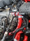
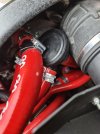
Firstly disconnect the brake servo line on the left hand side of the inlet manifold, this will require you to cut the rubber that keeps this and the PCV 1st vacuum line snug together. If you cut it right, you wont damage the original system and can be reverted to stock whenever you like. You can remove the system very easily without having to damage to original setup.
You will have to use a set of cutting pliers to remove the one-time-only use hose clamps. There will be two, only remove the closest to the front, and the pipes will come apart like so.
Image for reference:

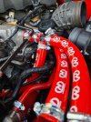
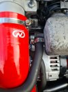
Once you have done this, there is a further pipe you will need to remove which is attached below to the 1st vacuum line into the inlet manifold, this again will require use of the cutting pliers / snips to remove the hose clamp.
Image below shows 1st vacuum feed.

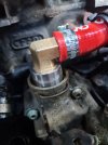
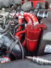
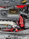
Now you will need to remove the CBV. You can clearly see it just behind the dipstick tube, above and to the left of the oil filter housing, the 90 degree pipe with a metal retaining clip.
To make this very easy, remove the dipstick but make sure you have a spare just incase it snaps. (The OEM dipsticks tend to snap and are very brittle). Once the dipstick is removed you can move any wiring looms out of the way, and you will want to lift up the GREY connector from its seat and move that out of the way to get easy access to the CBV.
Image for reference:

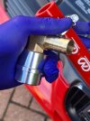
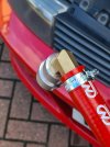
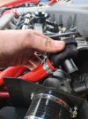
All you will need to do is use some slight force to remove the metal retainer clip on the pipe, and be very careful to wiggle the original plastic valve out of its seat. Make sure to take out the old O-ring too as this will have perished.
The seat for the valve will be covered in whitish/yellowish black gunk, use a lint free paper towel and some isopropyl rubbing alcohol to clean the area meticulously.
Images below for reference:


Now that the CBV seat / flange is all cleaned up and any debris removed, we can remove the rest of the PCV system
There is one more vacuum line in the center front of the inlet manifold that will need to be removed, and then blanked with a silicone blanking plug and jubilee clip / hose clamp.
This will require a bit of patience to remove, as it's a bit tricky without removing the inlet manifold. Just be patient with a pair of snips and eventually you'll get it off.
Images for reference:


Just to remind you, the pipe that needs blanking is at the front, in the center and just underneath the inlet manifold!
Once this has been done, you should be able to wiggle out the PCV pipework to the right and pull it all out. You will also need to remove the squid shaped hose located on the VCB. This is at the top of the engine on the right. Just remove all hose clamps and disconnect it all. Make sure to set aside the hockey puck for later, or you can leave the puck attached by disconnecting all connected hoses, apart from the one going into the TIP. I decided to remove mine as mine was incredibly perished and looked kinked.
Here is what the PCV system should look like out of the car.

As this is my first post on the forums, I'm going to talk about one of the first things I did when I purchased my Mk1 Leon Cupra R. There are so many indecisive guides and threads out there that either provide the wrong information, or haven't got enough info to actually understand how to install a Catch Can and the best way of doing so. I've looked on VWVortex, SeatCupra, AudiSport and plenty of other forums to decipher the correct way of doing it.
I haven't been here long, but I have used these forums so much recently to diagnose and fix problems with my motor, so I think it's time for me to give back.
There are many ways to install a oil catch can, many different types and also pros and cons of each. In this particular thread I'm going to talk about removing the original PCV system, and simplifying it with a Catch Can.
Let's first talk terminology;
'OEM' - Original Equipment Manufacturer
Self explanatory - the original piece of equipment or item provided at point of sale or purchase of car.
'PCV' - Positive Crankcase Ventilation.
Some may refer to a 'PCV Valve', however the PCV is a system comprised of many valves and pipes.
The PCV system as a whole removes gases such as unburnt fuel and oil vapors from the engines crankcase and on stock / oem systems will normally cycle the vapors back into the TIP to be re-burnt in the engine.
'Hockey Puck Accumulator Valve' - I'm not exactly sure the exact name of this part, however most people refer to it as a hockey puck due to the shape.
The hockey puck is supposed to help filter out the oil mist in the vapors that come out of the CBV and VCB before sending the rest to the TIP.
The hockey puck will also help to bleed air through during heavy vacuum.
'TIP' - Turbo Intake Pipe
This is the tube that runs from the airbox into the turbo)
'Catch Can'
This collects the unwanted oil and fuel vapors in the feed air via a set of baffles, accumulates the oily liquid and then returns cleaner air to the TIP or in some cases - vented to atmosphere. (This depends on the catch can you have purchased. I would advise a return to TIP as these don't spew oil, and will still pass MOT's. I will talk more about this later.
'CBV' - Crankcase Breather Valve
This is a 90 degree pipe that is located near the bottom of the crankcase which will vent some of the unwanted gases.
'VCB' - Valve Cover Breather
This is located at the top of the engine on the side, it's a small pipe that sticks out of the valve cover that will vent some of the unwanted gases.
Types of Catch Can
All catch cans do the same thing. They take away unwanted gases from the crankcase and valve cover and separate the oil and fuel from the air and will accumulate in the can/tank.
There are different options when considering a catch can;
1) Standard Catch Can - These just simplify the PCV system, the catch can will collect vapors, separate the oil/fuel mix and recirculate the clean air into the TIP.
2) Vent to Atmosphere - As it sounds, this will vent unwanted gases straight to the atmosphere instead of recirculating back into the TIP or accumulating in a tank.
3) Oil to Sump - These catch cans send the oil/fuel mix back into the sump where the oil is then recycled into the engine.
To learn more about the different types of catch cans, please watch the following YouTube video to decide which one is right for your needs -
I personally would recommend a standard catch can, that accumulates oil and vents the clean air back into the TIP. You can purchase the one I have from Creations Motorsport here:
Baffled Oil Catch Tank Kit 19MM Inlet & Outlet (Anodised) For 1.8T 2.0TFSI Cars
BAFFLED OIL CATCH TANK KIT 19MM INLET & OUTLET (Anodised) For 1.8T 2.0TFSI VAG CARS
creationsmotorsport.com
Installing a Catch Can on my 1.8T LCR 225hp (It is the same principle for all engines out there, but things may look different and be in different places)
Anything that I say that will be on one side of the engine refers to RHD vehicles, it will be the opposite on LHD vehicles.
Step 1) Removing 99% of the original PCV System
Firstly disconnect the brake servo line on the left hand side of the inlet manifold, this will require you to cut the rubber that keeps this and the PCV 1st vacuum line snug together. If you cut it right, you wont damage the original system and can be reverted to stock whenever you like. You can remove the system very easily without having to damage to original setup.
You will have to use a set of cutting pliers to remove the one-time-only use hose clamps. There will be two, only remove the closest to the front, and the pipes will come apart like so.
Image for reference:
Once you have done this, there is a further pipe you will need to remove which is attached below to the 1st vacuum line into the inlet manifold, this again will require use of the cutting pliers / snips to remove the hose clamp.
Image below shows 1st vacuum feed.
Now you will need to remove the CBV. You can clearly see it just behind the dipstick tube, above and to the left of the oil filter housing, the 90 degree pipe with a metal retaining clip.
To make this very easy, remove the dipstick but make sure you have a spare just incase it snaps. (The OEM dipsticks tend to snap and are very brittle). Once the dipstick is removed you can move any wiring looms out of the way, and you will want to lift up the GREY connector from its seat and move that out of the way to get easy access to the CBV.
Image for reference:
All you will need to do is use some slight force to remove the metal retainer clip on the pipe, and be very careful to wiggle the original plastic valve out of its seat. Make sure to take out the old O-ring too as this will have perished.
The seat for the valve will be covered in whitish/yellowish black gunk, use a lint free paper towel and some isopropyl rubbing alcohol to clean the area meticulously.
Images below for reference:
Now that the CBV seat / flange is all cleaned up and any debris removed, we can remove the rest of the PCV system
There is one more vacuum line in the center front of the inlet manifold that will need to be removed, and then blanked with a silicone blanking plug and jubilee clip / hose clamp.
This will require a bit of patience to remove, as it's a bit tricky without removing the inlet manifold. Just be patient with a pair of snips and eventually you'll get it off.
Images for reference:
Just to remind you, the pipe that needs blanking is at the front, in the center and just underneath the inlet manifold!
Once this has been done, you should be able to wiggle out the PCV pipework to the right and pull it all out. You will also need to remove the squid shaped hose located on the VCB. This is at the top of the engine on the right. Just remove all hose clamps and disconnect it all. Make sure to set aside the hockey puck for later, or you can leave the puck attached by disconnecting all connected hoses, apart from the one going into the TIP. I decided to remove mine as mine was incredibly perished and looked kinked.
Here is what the PCV system should look like out of the car.
Attachments
-
 20211103_110352.jpg356.6 KB · Views: 996
 -
 20211103_110604.jpg340.6 KB · Views: 986
 -
 20211103_111137.jpg554.4 KB · Views: 1,208
 -
 20211103_112957.jpg692 KB · Views: 1,302
 -
 20211103_130430.jpg644.3 KB · Views: 3,020
 -
 20211103_130426.jpg470.1 KB · Views: 3,067
 -
 20211103_130443.jpg475.6 KB · Views: 2,553
 -
 20211103_135021.jpg471 KB · Views: 1,381
 -
 20211103_121014.jpg373.2 KB · Views: 1,152
 -
 20211103_135027.jpg925.7 KB · Views: 3,918
Last edited: