Impulse speed sensor wiring assistance

tvrfan1

Guest
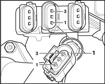
I have just attempted to replace the engine speed sensor (crank sensor) as VAG COM has told me that is the reason that it isn't starting. Unfortunately due to my ham fistedness I have pulled a connector clean off the loom. I can't attach a picture as I haven't done 15 posts. Basically the female side of the connector I have managed to pull off the loom. There are 3 wires that feed into it, brown, black and white. The connector has numbers on it, 1,2 and 3. Basically can anyone confirm what colours go with which numbers!

I am hoping someone has a workshop manual or a car on blocks that they can look at. The sensor is right next to the oil filter.

Any help will be welcomed! I am pretty sure I can take the connector apart to put the wires back in, but its going to be a horrible job!


Thanks,
Vince
 

tvrfan1

Guest
The connector that I pulled the brown, white and black wires from is part number 1j0 973 723 g - it looks like a standard connector - I have found them for sale on the net but I can't find anything that tells you how to put the wires back into the connector - anyone?!!
 

tvrfan1

Guest
No, there is only 1 crank speed sensor. I just mean it looks similar to other connectors, but connectors doing totally different jobs.

If all else fails I will ask in the Seat garage.
 

Pyro

Guest
I'll be out under tge car in abit I'll tryvto see if I can see what you mean bit can't promise

Sam
 

Ronin225

Active Member
Jan 17, 2008
4,652
22
Worcester
No, there is only 1 crank speed sensor. I just mean it looks similar to other connectors, but connectors doing totally different jobs.

If all else fails I will ask in the Seat garage.

For some reason i was thinking wheel speed sensor
 

Muttley

Catch that diesel!
Mar 17, 2006
4,987
31
North Kent
What's the layout of the pins on the sensor, and do they have any numbering?

The earth pin should be number 1 (editted to correct it, I had 3 earlier), and have the black wire.
 
Last edited:

tvrfan1

Guest
The sensor has all three wires going in but there is no way of knowing which wire goes to which pin. I have cut up the old connector and stripped the wire back and it has one bare core and a black and white wire, but I don't think that this HAS to be the same as the wire colours used on the other side of the connector (probably but I wouldn't want to risk it).

Muttley - how do you know that pin 3 is earth?
 

Muttley

Catch that diesel!
Mar 17, 2006
4,987
31
North Kent
Elsawin. Tells me there's a wiring harness connector "on radiator" and shows pin 1 as a black earth wire connected to the screen. That's pin 1 connected to earth, I got it wrong in my last post (and will edit to correct it).

Pin 2 is brown and 3 white, both going to the ECU.

If you can trace the wire back and find the connector then there's a chance you might find the short bit of harness in a scrapyard, assuming they have them in Saudi Arabia.

Edit: which connector is it you've broken, the one connecting to the sensor or one further back?
 
Last edited:

Muttley

Catch that diesel!
Mar 17, 2006
4,987
31
North Kent
Can you describe the layout of the speed sensor, the wiring and the connectors? Elsawin seems to tell me the sensor is hard-wired to the center of a block of three connectors, and connects to a white plug. If that's so, Elsawin has a diagram of the connector that will tell you which end is No.1. However if you can look at the wires going into the connector from the sensor itself, they should maintain the black/brown/white colouring and tell you for sure which wire to connect to which pin.
 

tvrfan1

Guest
Hi,

I expected the connector to be in the middle of three connectors, as I have seen on the internet and when I asked at the SEAT garage. They even gave me a print out showing that it was a white/gray connector in the middle of three others. But when I have come to do the job the connector is not very far from the sensor itself, the wire between the sensor and the connector is only about 200mm's. I had exepcted it to be much longer.
The connectors that I expected to see 3 abreast aren't there, there is only 1 connector. When I got the print off from the SEAT garage I took the VIN off a 2003/4 car that was in the workshop...I am wondering if the earlier cars had a slightly different arrangement (my car is 2002).

Thanks for all your help with this guys!
 

tvrfan1

Guest
Edit: which connector is it you've broken, the one connecting to the sensor or one further back?[/QUOTE]

The one further back - it is the connector which attaches to the actual harness.

I need help with how you put the wires back into the connector too to be honest! I think that will have to be a conversation with the mechanic at the garage. I have found the connector for sale on the net but I can't find any reference to how it actually connects the bare wires into the connector itself.
 

tvrfan1

Guest
Can you describe the layout of the speed sensor, the wiring and the connectors? Elsawin seems to tell me the sensor is hard-wired to the center of a block of three connectors, and connects to a white plug. If that's so, Elsawin has a diagram of the connector that will tell you which end is No.1. However if you can look at the wires going into the connector from the sensor itself, they should maintain the black/brown/white colouring and tell you for sure which wire to connect to which pin.

That is definitely the right connector - it is a white connector. If you can post the diagram or email it to me or something that would be legendary. I just have to figure our how to put it back together then. It feels like I might be getting somewhere now though...
 

tvrfan1

Guest
Lads,

skived off work and went down to the SEAT dealers, they had some engines and looms kicking around and they have cut a connector off for me. It turns out the colours and numbers were: 1. white 2. brown and 3. black.

I will get to work soldering it all up tomorrow morning or tonight if its not too hot - its 46 degrees C at the moment...

Cheers for all your help guys,
 

Muttley

Catch that diesel!
Mar 17, 2006
4,987
31
North Kent
Here's the drawing showing the numbering of the connector pins.

Speedsensorplug.jpg


Pin assignments: 1 - black - earth
2 - brown - Hall sensor to ECU
3 - white - Hall sensor to ECU

The colours should be the same either side of the connector. However I do understand that disassembling them is not easy.

If you've bought a new connector it should come disassembled, and you just need to crimp or solder the wires to the metal contacts then push them into the body of the connector. They are usually designed with one-way spring tags so that they can be pushed in but resist being pushed back out again. I've never disassembled one of the VAG connectors so I don't know their internal construction.
 

tvrfan1

Guest
Soldered it all up and now the immobiliser is stopping it starting. Devastated.
 
SEATCUPRA.NET Forum merchandise