
-
Hey Guest👍👎 We're looking for reviews of your local CUPRA or SEAT Dealership - it's quick and easy to do: Leave a review now
You are using an out of date browser. It may not display this or other websites correctly.
You should upgrade or use an alternative browser.
You should upgrade or use an alternative browser.
ian_cupra
Guest
they dont advertise it, cos they make them in house and wouldnt be able to keep up with demand
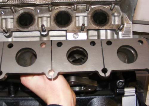
i dont have a gasket to hand no, i'm gonna take my standard manifold off and try that gasket on it
i dont have a gasket to hand no, i'm gonna take my standard manifold off and try that gasket on it
Sch pipe fittings.
choices are 1.25" NB or 1.5" NB - Assume a thick wall fitting in Sch40
1.25" NB fitting - OD is 42.2mm with 3.56mm wall thickness (35mm ID)
1.5" NB fitting - OD is 48.3mm with 3.68mm wall thickness (40.94mm ID)
What diameter do the ports on the head flange measure?
info here>> http://www.aalco.co.uk/literature/literature.html#stainless
Full-Race picture here> which is deffo 1.5"Sch40 fitting size.
Last edited:
they say that the manifold gasket is the same size as the ports on there maniold, which makes my standard one far to big!
The gasket should be the same as the port size mate!
they say that the manifold gasket is the same size as the ports on there maniold, which makes my standard one far to big!
std exh gasket is way larger. larger than the cylinder head ports by a couple of mm.
Wouldn't be so bad if they chamfered the edge to mate it up! Or just used larger diameter piping!
they dont advertise it, cos they make them in house and wouldnt be able to keep up with demand
Didnt think they did one for k03. How much was it?
ian_cupra
Guest
they dont make them really, i saw one they were making for someone else, so asked for one
Expensive was it?
ian_cupra
Guest
not measured it yet as havent got anything with me to measure until tomorrow at work, and yeah was fairly expensive 
JBS Alec
Guest
Right, let's sort this out guys. I know this is lengthy but if you want to go making comments along the lines of “engineering rubbish” as one chap has done you may as well read it so you can come back to me with your argument, which I’ll happily discuss.
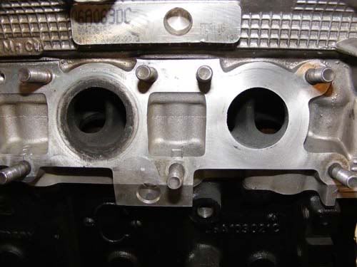
I have a test engine in front of me. The diameter of the port on the head is 33.5mm (to a tolerance of 0.2mm or there abouts). This is the same as the ibiza engine. I have the same style manifold in front of me as Ian’s'. The exhaust flange port diameter is 36.7mm (again to small tolerance for my callipers). If you're telling me that the one you have is less than 33.5mm then I will be very surprised, considering the laser cutting machines all work off one drawing, run off a CNC programme and the tolerance on the machine is +/- 0.1mm. So that is the dimensions cleared up.
Next let’s talk about the design itself. All pipes have losses. There are two main types of drag in fluid flow (it is a fluid before anybody claims what we have here is 100% gas with no moisture content), pressure drag and friction drag. All we can really do about friction drag is choose a low relative roughness (height of roughness/diameter) so we choose 316L which is pretty good and still has good material properties to deal with heat and load.
Pressure drag we can do something about. Head loss down a pipe depends on lots of things. If both ends of the pipe and at the same elevation, then velocity, diameter and friction factor are the main contributors. Friction factor is calculated on a moody chart using Reynolds number and relative roughness. Reynolds number depends on density, velocity, diameter and viscosity. This is for a straight pipe. More importantly, losses also occur at elbows and sudden expansions and contractions. Note sudden expansions, if you have a small port on the head, followed by a large port on the manifold that is a sudden expansion, therefore a loss. The stock manifold then squeezes up which is a contraction. Another loss. The JBS manifold is a CONSTANT diameter. Apart from the slight difference (manifold port 3mm larger) at the head it is a constant diameter from the head port to the collector. Also the Reynolds number will always be larger than 10^5 so we are always going to be dealing with turbulent flow, best case scenario transitional.
So the next problem is velocity. Velocity of the gas is important to spool the turbo. Mass flow rate is constant so using continuity the larger the port the SLOWER the velocity. You have to be careful because you can’t just make the ports super small because it then won’t flow at the top end (high revs, largest mass flow rate and largest velocity) because pressure drag will go up. It is possible to optimise diameter over a given length but this requires the budget of F1 teams and would mean the manifolds would cost a little more than £450. For this reason it is sensible to apply the knowledge as reasonably as possible and make the decision about what the diameter will be based on the sizes of available materials. What is the point in specifying a diameter if you can’t make it. That is why they are the size they are. Anyway why does it matter if the flange hole is smaller than the gasket? What matters is the size of the head ports.
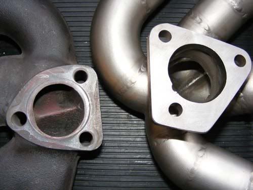
Also, compare the collectors. I will upload a photo comparing them shortly and you will notice this is where there is a huge difference. Obviously in favour of the JBS design. Finally what is the point of the manifold flowing tons and tons of volume if the turbine housing is tiny and a far bigger restriction than the JBS manifold anyway.
I’m not being arrogant here guys but I need to get this across. I’m protecting my integrity, and that of JBS Auto Designs. Let’s hear back guys if you want to ask any more questions.
Alec
I have a test engine in front of me. The diameter of the port on the head is 33.5mm (to a tolerance of 0.2mm or there abouts). This is the same as the ibiza engine. I have the same style manifold in front of me as Ian’s'. The exhaust flange port diameter is 36.7mm (again to small tolerance for my callipers). If you're telling me that the one you have is less than 33.5mm then I will be very surprised, considering the laser cutting machines all work off one drawing, run off a CNC programme and the tolerance on the machine is +/- 0.1mm. So that is the dimensions cleared up.
Next let’s talk about the design itself. All pipes have losses. There are two main types of drag in fluid flow (it is a fluid before anybody claims what we have here is 100% gas with no moisture content), pressure drag and friction drag. All we can really do about friction drag is choose a low relative roughness (height of roughness/diameter) so we choose 316L which is pretty good and still has good material properties to deal with heat and load.
Pressure drag we can do something about. Head loss down a pipe depends on lots of things. If both ends of the pipe and at the same elevation, then velocity, diameter and friction factor are the main contributors. Friction factor is calculated on a moody chart using Reynolds number and relative roughness. Reynolds number depends on density, velocity, diameter and viscosity. This is for a straight pipe. More importantly, losses also occur at elbows and sudden expansions and contractions. Note sudden expansions, if you have a small port on the head, followed by a large port on the manifold that is a sudden expansion, therefore a loss. The stock manifold then squeezes up which is a contraction. Another loss. The JBS manifold is a CONSTANT diameter. Apart from the slight difference (manifold port 3mm larger) at the head it is a constant diameter from the head port to the collector. Also the Reynolds number will always be larger than 10^5 so we are always going to be dealing with turbulent flow, best case scenario transitional.
So the next problem is velocity. Velocity of the gas is important to spool the turbo. Mass flow rate is constant so using continuity the larger the port the SLOWER the velocity. You have to be careful because you can’t just make the ports super small because it then won’t flow at the top end (high revs, largest mass flow rate and largest velocity) because pressure drag will go up. It is possible to optimise diameter over a given length but this requires the budget of F1 teams and would mean the manifolds would cost a little more than £450. For this reason it is sensible to apply the knowledge as reasonably as possible and make the decision about what the diameter will be based on the sizes of available materials. What is the point in specifying a diameter if you can’t make it. That is why they are the size they are. Anyway why does it matter if the flange hole is smaller than the gasket? What matters is the size of the head ports.
Also, compare the collectors. I will upload a photo comparing them shortly and you will notice this is where there is a huge difference. Obviously in favour of the JBS design. Finally what is the point of the manifold flowing tons and tons of volume if the turbine housing is tiny and a far bigger restriction than the JBS manifold anyway.
I’m not being arrogant here guys but I need to get this across. I’m protecting my integrity, and that of JBS Auto Designs. Let’s hear back guys if you want to ask any more questions.
Alec
Last edited by a moderator:
JBS Alec
Guest
JBS Alec
Guest
The picture below shows the size difference between a standard manifold port size and the head. This can be see by the black mark around the edge.
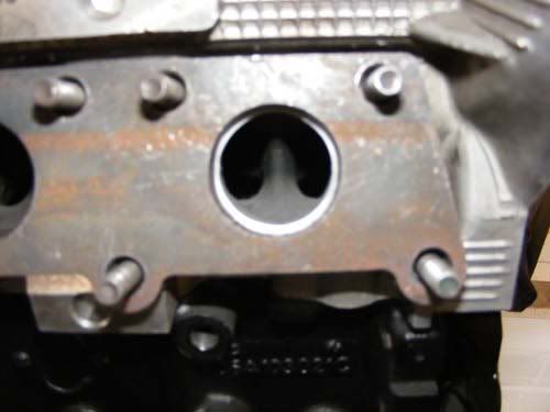
This picture shows the JBS flange, a much better fit.
This picture shows the JBS flange, a much better fit.
so James, you are saying you are using 1.25" SCH40 fittings by definition on this k0x manifold hence the difference in apparent size to OE manifold. (other posted sample of JBS IHI one having larger size, being 1.5" SCH40 fittings (which is befitting the higher flow rate from an IHI type turbo)
Yes, there's more to flow than size alone stating the obvious.
Some small step from cyl head to pipe runner is good for pulse tuning/anti-revirbiration
Yes, there's more to flow than size alone stating the obvious.
Some small step from cyl head to pipe runner is good for pulse tuning/anti-revirbiration
Last edited:
JBS Alec
Guest
Hi Bill,
It's Alec here, and yes it is Shed 40 1 1/4". It doesn't matter whether it's different from OEM or not. OEM is not performance orientated. OEM has that converging runner style otherwise the turbo would be completely unresponsive. CFD (I use fluent and gambit) has shown as far as reasonably possible that this is the closest to optimum diameter. But you have to engineer to build, so shed 40 1 1/4" is the closest available size so that's what I use, and have bent to the angles required.
Regards
Alec
yes vs the available pipe fittings you also mentioned.. The point for folks generally being the K0x manifold is sized to the ports and K0x turbo.
interesting post over on vortex on stock manifold runner flows.

compared to a larger bore cast version

interesting post over on vortex on stock manifold runner flows.
compared to a larger bore cast version
JBS Alec
Guest

Similar threads
- Replies
- 1
- Views
- 525
- Replies
- 57
- Views
- 9K