• Hey Guest💡👉 We have just launched our new Dealer Directory and review service Find out more now

silver123

Active Member
Apr 2, 2007
56
0
I don't know how crankcase ventilation is done on this engine. It should be done like this schematics show
stock_pcv.jpg

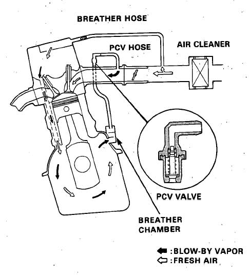
but I can't find any crankcase connections.
I make a photo of the engine bay where I think one of the connection of PCV is.
6sg-P10300.jpg

The rubber pipe maked with red bigger square should be the higher pressure point and air should be sucked here, but instead if you disconnect this it blows off. There is also some other samller rubber pipe (marked with smaller square) that comes from intake manifold to here as seen on the pic. The third rubber pipe (marked with red circle goes to charcoal filter and is used for something else).
 
the hose that is blowing air out is right, the idea is to take pressure away from the crankcase as opposed to increasing it iirc

There shouldn't be ayn pressure in the crakcase since it should be open system. The idea of crankcase ventilation is to ventilate gases that smuggle throug pistons rings out of the crankcase and back to air intake, because they contain unburned hydrocarbons that are harmfull to engine oil.

Physics fact is that gases will flow from higher point to lower point of pressure and pressure before throttle plate is allways higher that behind it, so it is not logically that air will be blowing out there.

The basic PCV system is shown on the schematics - KEEP THAT IN MIND!
 
There is one connection to ventilate the crankcase, made to the oil filler cap on the rocker cover of the AKL engine. That's the hose you have identified with a large rectangle.

That's all that is needed, a means of routing excess pressure in the crankcase (from blowby gases etc.) to the inlet system so that the fumes are consumed in the engine and treated by the exhaust catalyst.

Despite what they may say in Wikipedia or at the Honda Integra Club, not every engine has a fresh air connection to the crankcase. KEEP THAT IN MIND.


The charcoal filter is vented to the intake system for emission control purposes, which is why it is connected to the throttle body.

The last pipe could be anything, a vacuum takeoff, a connection to the variable-length manifold change-over actuator, or something else entirely.
 
Despite what they may say in Wikipedia or at the Honda Integra Club, not every engine has a fresh air connection to the crankcase. KEEP THAT IN MIND.
Sorry mate for my arrogation, I really thought that the only way is described above.


The charcoal filter is vented to the intake system for emission control purposes, which is why it is connected to the throttle body.
That I know.

The last pipe could be anything, a vacuum takeoff, a connection to the variable-length manifold change-over actuator, or something else entirely.
It is not a connection to the variable-length manifold change-over actuator since this is on the other side of the intake manifold. It also isn't vacuum takeoff for brake container since this pipe is lower, but I can tell that engine idle is very rough if you disconnect this pipe.

BTW do you think crankcase pressure will be high enough to overcome the boost of 0,2 bar?
I am only asking this since I have an idea to add KO3 turbo to this engine. (the engine will not be fitted to any car, the only reason is experimentation.)
 
Last edited:
QUOTE=silver123 wrote

Sorry mate for my arrogation, I really thought that the only way is described above.

I get the impression English isn't your first language? (If not, I apologise, but that is how your writing style and sentence construction comes across). If so, you are doing very well in a foreign language, better than I could. You should put your country of origin in your profile so that we can be a bit kinder :)


It is not a connection to the variable-length manifold change-over actuator since this is on the other side of the intake manifold. It also isn't vacuum takeoff for brake container since this pipe is lower, but I can tell that engine idle is very rough if you disconnect this pipe.

Connection to the fuel pressure regulator?

BTW do you think crankcase pressure will be high enough to overcome the boost of 0,2 bar?
I am only asking this since I have an idea to add KO3 turbo to this engine. (the engine will not be fitted to any car, the only reason is experimentation.)


Definitely not. The ventilation system relies on the fact that there is always some pressure drop in the inlet duct. You would need to move the breather hose connection to the inlet side of the turbo.

However that won't be the biggest problem. You will need to remap the ECU to recognise the difference in air delivery of the turbocharged system.
 
I get the impression English isn't your first language?
It also isn't my second one, english is my third language or second foreign and spelling isn't my virtue.

Connection to the fuel pressure regulator?

Can't really tell, since I should remove the intake manifold. All I can see now is that the pipe goes somewhere to the intake manifold.


However that won't be the biggest problem. You will need to remap the ECU to recognise the difference in air delivery of the turbocharged system.
Yes it can be the problem. The idea was to change the original ECU with one found in 1.8T engines, since those have aslo the N75 output signal. Don't know if other sensors and injectors are even compatibile to connect to it.
Remapping shouldn't be that big of a problem (I hope).
 
I can think of one sensor you will not have, the Manifold Absolute Pressure sensor (MAP), (not to be confused with the Mass Air Flow sensor (MAF) which you do have).

Your intake air temperature sensor is also combined with the MAF, and turbo engines need to know the temperature at the inlet manifold.

If one have an idea to add a turbocharger to an NA engine then adding MAP or EGT sensor isn't really the biggest problem.
And I am not sure all turbos have MAP since I also have an old VW Passat with 1.8T engine (AEB) and I don't have any MAP data when I connect it on VCDS. As I know modern MAF sensors are allways in a combination with IAT since it has two termistors and one is connected to the NPN transisor base so the internal resistance of a hot wire is constant and current flow changes.

The biggest problem adding turbo to NA engine is exhaust system - tubo will not fit between the existent exhaust collector and downpipe and since you can't buy the aftermarket collector that will fit, the only solution is to order custom made (that can be more € than a new vehicle is). The other problem is turbo shaft lubrication (NA engines don't have the needed oil connections) and water cooling.
Then original fuel injectors can only take a few % higher fuel flow, so they should be changed with bigger ones to assure the required fuel flow. And since NA engines have higher compression ratio (round 10) the air-fuel mixture will self detonate if you wont cool it with extra fuel or water. Also you can't lower AFR above 13, since engine will be flooded.
The difference with 1.8 turbo engine is that it aslo has variabile valve timing and does not have variabile lenght intake manifold like AKL. Adding turbo to AKL engine will not mean much if you won't change at least camshaft.

But it is much bigger challenge (fun) than just remapping a turbo engine.
 
Last edited: