cairus

Active Member
Jun 4, 2024
1,748
619
Nachdem meine Fahrprofilauswahl dem PLA weichen musste, kam ich spontan auf die Idee, es anders umzusetzen.

Ich installiere jetzt folgende Einheit:
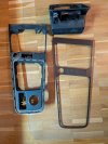
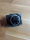
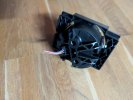
575927531G

576863283BD----> ich brauche nur das Teil mit dem Loch für die FPA

Schaltbild

LIN 1 (blau/lila) Gateway ---> FPA T4b/Pin 1

KL 30a (weiß/rot) ---> FPA T4b/Pin 2

KL 31 (braun) ---> FPA T4b/Pin 3

Der ursprüngliche FPA-Button wurde von der PLA bereits deaktiviert.

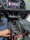
Dann die Installation. Ich werde hier Details veröffentlichen, sobald sie abgeschlossen ist. Die Codierung auch
 
Last edited:
When I had Leon, I was planning to retrofit PLA too.
But my plan was to use the right side of the switch group.
Originally I had Drive Mode, Start/Stop and Park Pilot buttons on the left, and only passenger airbag warning light on the right, without any button.
There is another right side switch group available with the ESC Off button and the passenger airbag warning light and I was thinking about to use it.
I heard that it is possible to clear the existing symbol (ESC Off) and put a new symbol (PLA) on the button using some laser etching technology and there are companies who provide this service. So this way I wouldn't lose any button from the left side.
 
I even have a laser at my disposal. Be careful, ESP switches on KL15, but the PLA needs KL31.

Actually, I don't need a driving profile selection, but thought if I have disassembled the car because of various cables etc. why not test the Ateca button
 
  • Like
Reactions: serdar_18fr
When I had Leon, I was planning to retrofit PLA too.
But my plan was to use the right side of the switch group.
Originally I had Drive Mode, Start/Stop and Park Pilot buttons on the left, and only passenger airbag warning light on the right, without any button.
There is another right side switch group available with the ESC Off button and the passenger airbag warning light and I was thinking about to use it.
I heard that it is possible to clear the existing symbol (ESC Off) and put a new symbol (PLA) on the button using some laser etching technology and there are companies who provide this service. So this way I wouldn't lose any button from the left side.
I've wrote about that on another thread, but PLA needs button with two diodes (red and orange) in order to work properly. To be precise it only requires single diode which indicates that Park Assist is active. So you have two options:
  • sacrifice button illumination in night and use red diode to indicate Park Assist activation
  • install button with two diodes
You can merge three different button sections into one to achieve second option (see spoiler). Pinout looks like this:
  • 1 - ground
  • 2 - red illumination - KL58d from other buttons
  • 4 - orange illumination - 4th pin in 26-pin PLA 3.0 module
  • 5 - Park Assist activation - 3rd pin in 26-pin PLA 3.0 module
Also it does not fit perfectly, but you can use right blank button from 5F0927137 to engrave your icon.

1746009451850.png

1746009723734.png

1746009714880.png
 
  • Like
Reactions: serdar_18fr
I've wrote about that on another thread, but PLA needs button with two diodes (red and orange) in order to work properly. To be precise it only requires single diode which indicates that Park Assist is active. So you have two options:
  • sacrifice button illumination in night and use red diode to indicate Park Assist activation
  • install button with two diodes
You can merge three different button sections into one to achieve second option (see spoiler). Pinout looks like this:
  • 1 - ground
  • 2 - red illumination - KL58d from other buttons
  • 4 - orange illumination - 4th pin in 26-pin PLA 3.0 module
  • 5 - Park Assist activation - 3rd pin in 26-pin PLA 3.0 module
Also it does not fit perfectly, but you can use right blank button from 5F0927137 to engrave your icon.

Nice & useful information, not for me anymore, but for anybody who could be interested in doing this retrofit.
???
 
So, the panel arrived on Monday and I took it apart. Unfortunately, the structure is different than I expected. But I'm sure I'll find a solution.
 

Attachments

  • PXL_20250507_184025887.jpg
    PXL_20250507_184025887.jpg
    780.4 KB · Views: 84
So, the " Driver Profil dial" is here

now the pinout where I'll connect it:

Air conditioning connection J255

J255 T20b/16 LIN 1 blau lila WRONG!!!

J255 T20b/13 LIN1

J255 T20b/20 KL30a red yellow

J255 T20b/19 KL31 brown
 

Attachments

  • PXL_20250509_184142944.jpg
    PXL_20250509_184142944.jpg
    374 KB · Views: 87
  • PXL_20250509_184147224.jpg
    PXL_20250509_184147224.jpg
    401.9 KB · Views: 83
Last edited:
  • Like
Reactions: grabania
So, there's an error in the connection plan. The LIN belongs to the gateway pin 13.
 
In addition, the data set must be adjusted so that the rotary knob works.
 
Dataset available upon request. I have now removed the panel and am considering integrating
 
  • Like
Reactions: gabz
The installation was not quite planned, but my daughter thought she had to drill the hole ?
 

Attachments

  • PXL_20250514_190655658.jpg
    PXL_20250514_190655658.jpg
    224.4 KB · Views: 93
Assembly begins. The LIN signal is present in my facelifted 2017 model, only at gateway pin 13 and control unit 16. Otherwise, no other connections. It works flawlessly.
 

Attachments

  • PXL_20250516_183251848.jpg
    PXL_20250516_183251848.jpg
    168 KB · Views: 84
  • Like
Reactions: gabz and maurobap