MAP Sensor has resistors?!

jaypee

Active Member
Mar 26, 2009
174
0
Ok I brought this up a while ago, but still haven't had much luck on this... my IHI has some resistors on the MAP sensor which we think was to clamp the sensor and attempting to modify what the ECU reads? Anyway the resistors have broken and can't get replacements... so should I just wire it back to standard?
I do have adjustable boost in the car, so maybe its so that runs ok...?
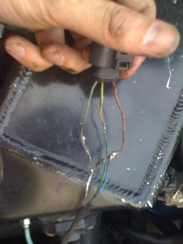
also could anyone tell me which colours go where because the wires on the socket dont match up with the wires on the loom...
Pic below!
3909611209_8f0b303462.jpg
 
Last edited:

jaypee

Active Member
Mar 26, 2009
174
0
also has anyone got one of these connectors? mine looks like its had better days!
 
Jan 8, 2007
2,958
1
Wiltshire
WTF has been going on there, do you know who did that to the car? If so I'd be having a word with them. If it were me I'd wire it back in properly without any resistors then do some logging to see if everything performs as expected.

Not got a connector but I've got a working MAP sensor if you need one. PM me if so to avoid breaking any forum rules.
 

EZ Tutty

Active Member
Nov 21, 2006
417
0
Derby
www.eztutty.co.uk
if thats the MAP Clamp mod, then it'll be more than likely a 4.7v Zener Diode, however if you remove it and put things back how they were then it the boost will be fully under the ECU's control and therefore dependent on the mapping.
 

jaypee

Active Member
Mar 26, 2009
174
0
Its definately not a diode in there. Definately two resistors!
I tried finding replacements but can only find one of the two as most of the places I tried don't seem to stock 6 colour band resistors. 1-4 is resistance 5th band is Tollerance and I think the last band is Temperature Coefficient...
I thought diodes looked like this?
1.5KE%20AXIAL%20SERIES.jpg

I'm gonna try a higher bar MAP and see if this solves the issue...
 
Jan 8, 2007
2,958
1
Wiltshire
Did you try RS Components for the resistors?

I'm not sure if it's the MAP sensor or ECU that can't see above 2.5 bar on the ME7s? Probably the sensor I guess, though either way it won't resolve your issue, potentially only making it worse by my understanding. It's the deviation limit that needs controlling which can be mapped out.

I'd be looking to speak to the person who set this up and also the mapper if known. This should be done the proper way.
 
Last edited:

jaypee

Active Member
Mar 26, 2009
174
0
I did actually, I'm gonna have another go at finding them this weekend.
Apparently (please correct me if im wrong on this) MAP sensor feed back voltage up to 5v or something, if you get a bigger MAP that does e.g. 3 bar it still reads up to 4.7volts but obviously reading more boost. so a 2bar MAP will read 4.7volts at max pressure and a 3bar MAP will read 4.7 volts at max pressure... And I assume anything higher gives out something like 5v and then we get LIMP mode?

It was Jabba who set it up yeaaaaaaaaaaaaaaaaaars ago! Was there old blue demo car!
 
Last edited:
Jan 8, 2007
2,958
1
Wiltshire
That car is like the site slag lol

Yes the MAP sensor gives a voltage output between 0-5v, 5v being 2.5 bar (remembering 1 bar is atmospheric)

Changing the sensor isn't going to stop limp mode though. The ECU takes the output of the MAP sensor and compares it to the specified boost level that the map requests and if they are not within a preset standard deviation then you'll hit limp mode. It's the map that needs sorting out to stop this happening. Using resistors to fool the ECU is just working around the issue as a bodge in my eyes.
 

jaypee

Active Member
Mar 26, 2009
174
0
Haha, the car was such a mess when I got it! Will get some pics up in time of how terrible it actually was!

Well a new MAP sensor is already on order, will get that fitted, remove the resistors and get the car in for remap.

Hopefully then we might have some luck, thanks for the help robbie and ez
 

ibizacupra

Jack-RIP my little Friend
Jul 25, 2001
31,333
18
glos.uk
jabba did this to work with their boost controller which also tapped into the map sensor output signal - it was done to keep ecu unaware of deviations so far as I know
 

jaypee

Active Member
Mar 26, 2009
174
0
Could I remove the boost controller and resistors then? Or would this cause even more havoc?
 

jaypee

Active Member
Mar 26, 2009
174
0
Funnily enough I did have a conversation with them yesterday (Brian that is, and I think Mike in background). They couldn't remember off hand what resistors they were (I think the car last came into them back 4 years ago in a very sorry state). They did mention that it wasn't something they installed like this anymore.
I think i'll just have to pull everything out and start from scratch, probably easier than messing around.
One question tho, why would my MAP Sensor connector/socket have different coloured wires on it to the wiring loom? Is the bit of wiring loom on the car possibly hand done via the boost controller?