Leon Cupra project “The Black Mamba” 800++ HP 1.8t build(engine assembly page 9)

Talx

Active Member
Nov 29, 2008
99
2
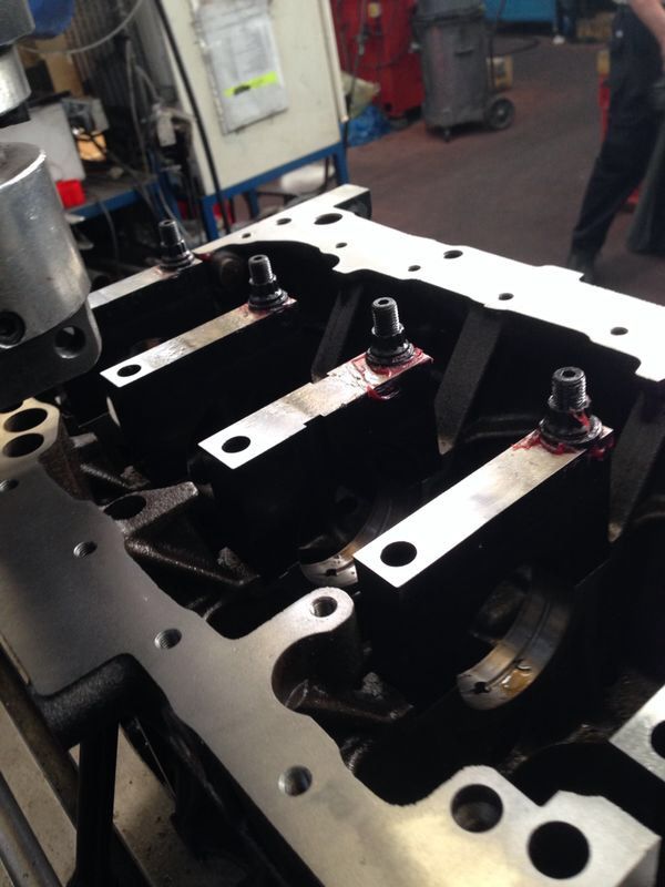
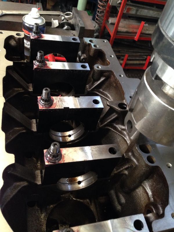
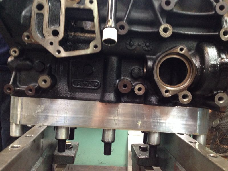
Got the engine block back from the workshop basically had the block bored an honed to 83mm both bottom and top decks surfaced and a line bore.it was a real pane according to the shop manager to install my billet mane caps even though I had CNC'd them from 4340 steel on an accurate CNC machine it seems they were not a perfect fit and had to have some work done to them to fit perfectly I guess on a production line I would have to rethink a few things over this is probably due to the engine block not being as symmetrical as we think and also I probably didn’t take into account the fact that the billet caps where less sustainable to stretching and compressing of the block on install, Also there was a complaint or two …. Something about the caps being very hard and the tools didn’t seem to be too happy with this. :)

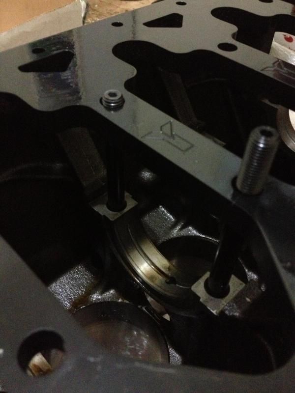
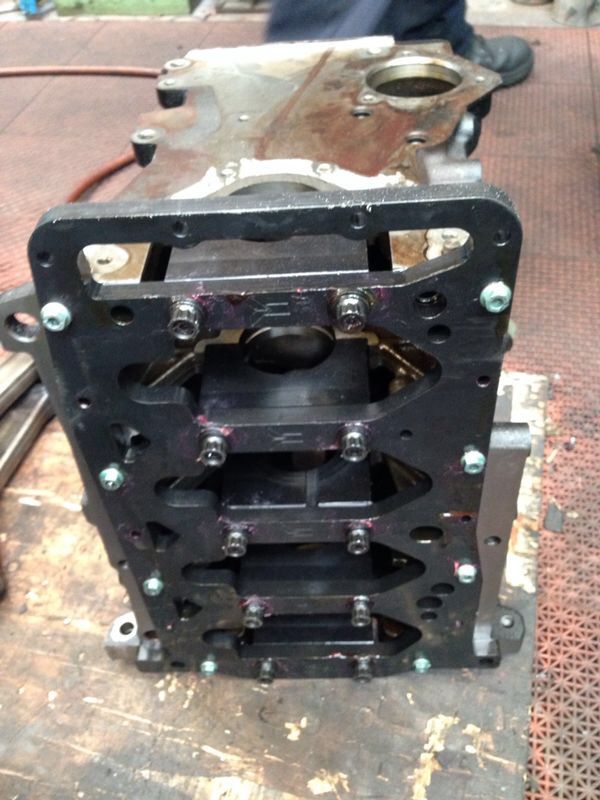
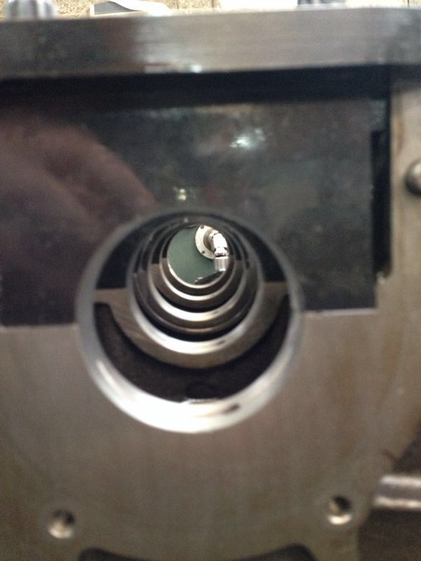
After fitting the main caps I had the bottom deck milled flat with the caps in order to accommodate the 4340 billet main girdle that i also make on a CNC and surfaced the top deck as well for a perfect head gasket seal. At the end of it all the block was bored out too 83mm and had a professional hone done to it as well. Needless to say that during the whole operation I had a torque plate mounted to the block with the head studs torqued to the correct ratings. You can also see the oil grove in the main bearing the I CNC'd into the block to help oiling the bearing at high RPM.


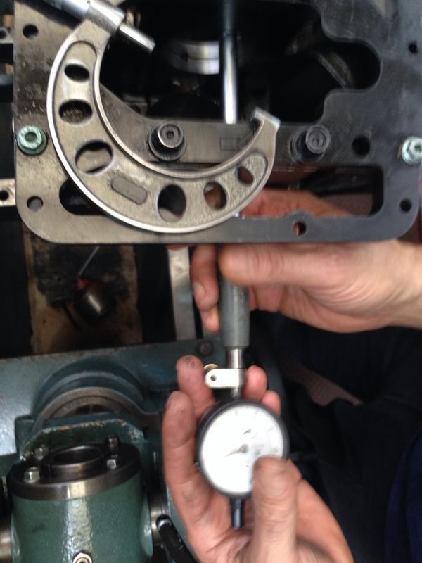
Sorry about the crapy pictures they were taken by the shop manager on some type of smart phone.


Last edited:

Talx

Active Member
Nov 29, 2008
99
2
After getting it back from the shop I pressure cleaned it using different sized brushes to clean out all the oil passages and scrubbed the block from any dirt and left over debries from the honing, best brush you can find to clean the cylinder hone from the dust that is trapped in the hone is a toilet brush LOL. This very important as this dust will get loose and kill your engine once started up.


Head is in the shop as well waiting for new intake seats for over size valves new valve guides and solid lifter calibration.

I hope to find the time soon to actually assemble the block will update once I do.

Accept for this I got one of our newly developed cast water flanges setup and we are very excited about this new product.


Talx

Active Member
Nov 29, 2008
99
2
Looks like I am in the final sprint to finish the engine build. Got the crankshaft balanced with the FW and the bolts, we balanced the crankshaft individually and then balanced it together with the FW. Actually the crankshaft was purity much balanced from the factory which was surprising since I did drill 5 extra bolts in it. We managed to get it down to a few milligram's in the end (forgot to picture the final balance shot).


Now it's all down to the assembly of the motor, I am starting with building the bottom end and later on the cylinder head.
I'm not going to bore you with the blue printing of the engine block since other people have covered this in the past to good detail of all the measurements and details involved in the procedure, obviously I have done it but I am only going to cover the technical stuff behind the build.

First thing was to install the engine bearings you can see the bottom half's I drilled in order to permit a higher rate of oil to the connection rods under high RPM operation, installed the crank, the billet engine block caps and the rear seal, I forgot that my oil pump was still of original height and that I need to skim 3mm off of it so basically I stopped the assembly work hear.


dowl pins inserted


I will explain, since the engine girdle is 12.5mm thick and the oil pump chain links are 9.5mm in length I had to take 3mm off of the pump in order to get the correct oil pump chain length, adding a link which is actually two parts adds 9.5X2=19mm to the length of the chain so I could have either added another link which would make it too long or just take 3mm off of the pump's mounting surface.
You can see the difference between the two pump used pump is original height and the new pump is skimmed 3mm.


The assembly of the bloke needs to be done in a correct order since I am installing an engine girdle I build which complicates things. First thing is the install of the front engine cover with oil ring , I am not able to install it because of the oil pump chain tensioner which will put tension on the chain and won't let me mount the pump since I welded the oil pump gear bolt. I have noticed the people did manage to install the cover first but with my setup and engine girdle it is not possible. Another thing I noticed was that since I am using a stretch gauge for the connection rod bolts I will need to install the rods and pistons and only then install the engine girdle and bolt down the crank and main caps, the problem is that the stretch gauge is interfering with the engine girdle. I will cover this when I install the pistons and rods. I also needed to skim the front engine cover a few tenths because the block was milled flat with the engine caps I build which stretch all the way up to the engine girdle surface to eliminate the need of spacers.

Next step will be installing the rods and pistons and bolting down the engine girdle.

Last thing is something I forgot to mention about the oil pump chain, since I needed to add links I also needed to close them to secure the chain, and well the tool was very expensive around 400$ for a professional too to close the links, so what I did was make myself my own tool. I did this by taking a spare lathe knife I had which is made of some sort of tuff metal doesn't mater really what, all I can say is I did make two tools prior to this one that where to soft and didn’t do the job of squashing the pin head. This is what I came up with one side with holes to hold the bottom part of the chain and the upper half with a v shaped slit in it in order to squash the pin head, I used a vise grip to apply the pressure and it worked like a charm.


Only new parts for now is the SQS-E I loved the mechanical version of the SQS sequential shifter so much that I decided to try out the newer electrical version.


Last edited:
Apr 12, 2008
1,197
1
Don't know how i missed this build...the title doesn't give away much, and i rarely trawl through readers rides. Brilliant work!
 

Talx

Active Member
Nov 29, 2008
99
2
Thanks for the feadback!

I changed the title maybe the new one is more informative. :)
 

Talx

Active Member
Nov 29, 2008
99
2
thanks mate! :)

Installed the rods, pistons and billet engine block girdle I designed.
Started off with inspecting the rods and pistons and assembling I already had filed the rings on an earlier date and piston matched them also all bottom end parts where matched and balanced. Before started installing the part I removed the center engine cap and installed it taking the correct measures to make sure that the cap is in place and that the thrust bearings where aligned, I have seen a few engines that had a thrust bearing failures because whoever assembled the engine didn’t install the main cap correctly
I installed the rods and pistons nothing special a set of Pauters and JE FSR 2618 forged pistons with tool steel wrist pins. I am using vandervell race bearing for the mains and rods


I used the ARP 83mm piston insert sleeve, cant install the piston easier than with this tool


I got my self ARP rod bolt stretch gauge basically it is much more accurate to set the preload of a bolt by the stretch than an inaccurate method of using a torque wrench that's accuracy has to do with many variabals.in the end I checked the stretch which was 0.0065" for the custom age 625 bolts which are intended for high RPM applications with the torque rating which was 90 NM and it came out purity accurate actually.


and then I noticed that the oil squerters where coming very close to the rods so I needed to bend the tips towards the pistons a bit, also I completely forgot to picture and document the modification I had to make to the oil squerters in order for them to work with my FSR pistons, basically I had to file the rear corner of the squerters base that comes in contact with the side of the block in order to be able to give them a bit of an angle so that they clear the pistons skirt. I installed them using 263 Loctite; we don’t want them getting loose on us. I also didn’t use the std TT225 oil squerters but instead got squerters from newer model tsi engines that already come with a bit of an angle in them already.

TT on left and tsi on the rghit


Next step I installed the oil pump ant front engine cover I tested how well the oil pump was sealing with the engine girdle with a feeler gauge and I could insert a 0.03mm leaf so I had to sand paper the oil pump mounting surface with a 1000 and 2000 grit to get it truly flat, this is funny since I did skim the mounting surface professionally by a machine shop.
I need to fix the oil pan dip stick hole because it is a bit off, I will do that tomorrow and install the oil pan and oil filter housing.

 
Last edited:

kevlaa

Altea Stylance / Arona FR Evo
Oct 12, 2010
274
5
s.wales
Your work is so impressive, I take my hat off to you! I can't wait for you to finish it!
 
Lecatona HPFP (High-pressure Fuel Pump Upgrades)