Boot Light and Glovebox Light Parts list and vague instructions...

nph

Guest
hello there,
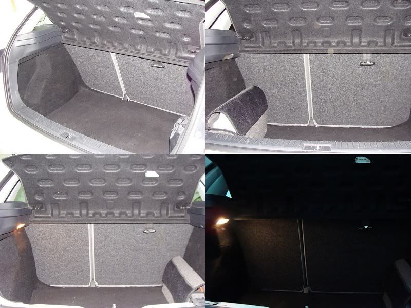
i've started the boot-light project before reading this thread. my ibiza came without boot-light or glovebox light, so after some thinking i've decided to start installing one.
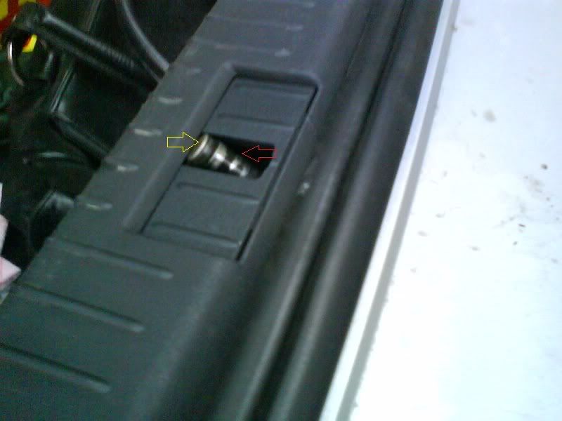
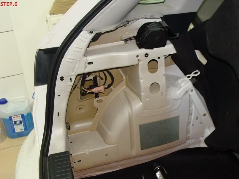
i've purchased the plastic trim with the light bulb and the support for the light bulb.
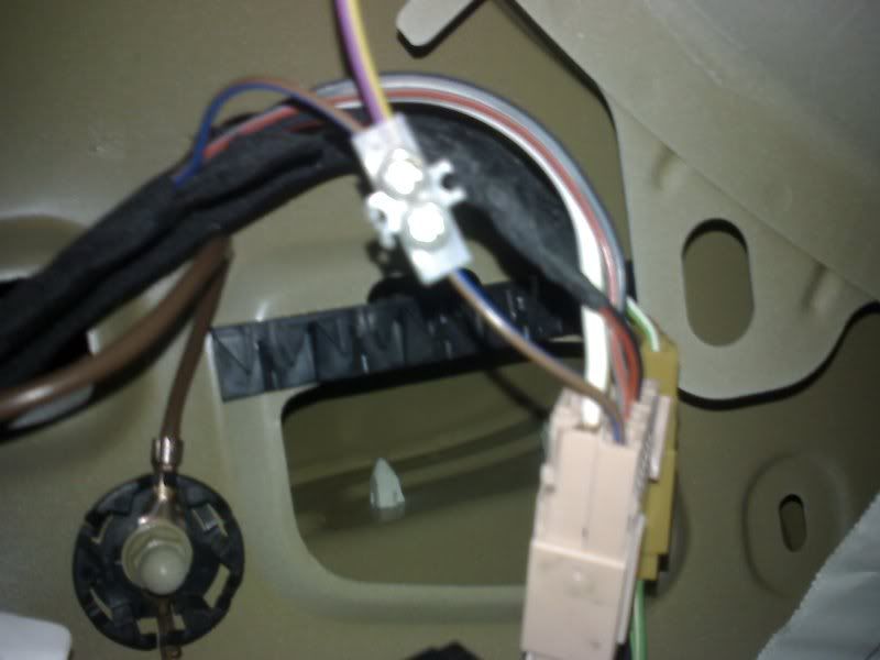
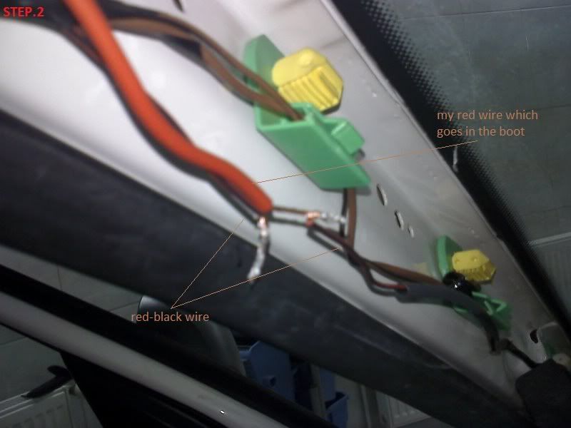
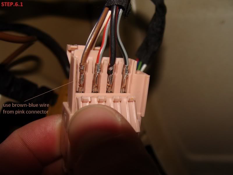
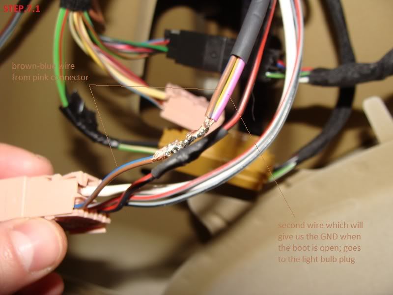
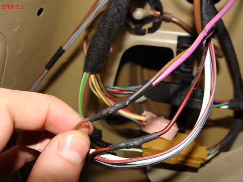
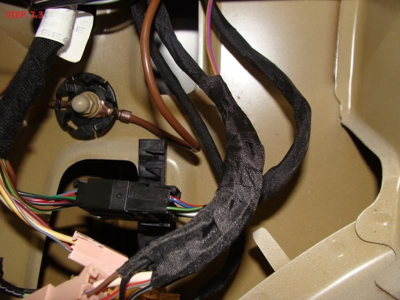
a friend told me what wires power the light (that is brown-blue and red-black) and after looking in the boot compartment i've found the pink connector were the wires are found an connected the light to it.


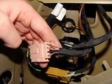
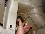
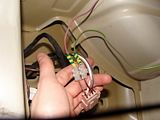
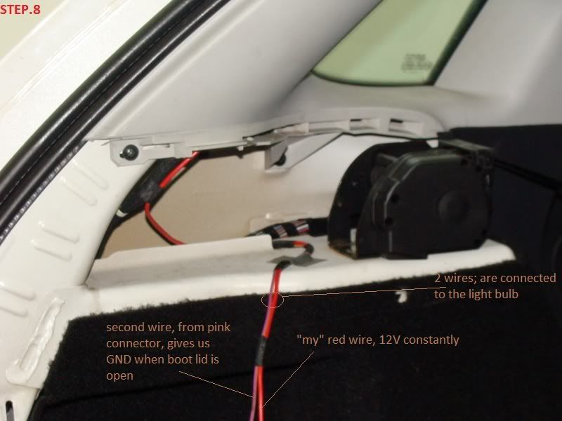
BIG problem, as you can see in the picture the red-black wire i used isn't the one needed. after measuring with a voltmeter there is only 3.5V on those wires, so i need to connect the red-black wire from the interior light.
how can this be done? which route would you thing would be easier? anyone know what is the red-black wire from the pink connector for, the one that i've used?

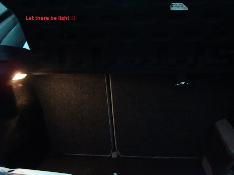
i am willing to finish this project and after i will do a diy, for others to see.
any advice is welcomed!
 
Last edited by a moderator:

BlackFR

Full Member
Jan 22, 2002
1,724
5
Not too far away
You are taking a wire from the Red/Black connection to the interior light at the front of the car all the way to the boot and connecting to that to the new light and then the other side of the new light to the brown / blue wire on the pink connector aren't you?

From your pic it looks like you are attaching to two wires in the pink connector which is not correct.
 

nph

Guest
the red-black wire from the pink connector was a bad choise, but was the one that i thought of at the moment, before reading the thread.
so, i need to take the wire from the interior light, out in the front, but i don't know which route to take, which is easier?

an before soldering bag the red-black wire from the pic, i would like to know what is it for, any ideas?
 

BlackFR

Full Member
Jan 22, 2002
1,724
5
Not too far away
I went down the passenger side of the A pillar into the glovebox light, along the passenger side trim panel and into the boot. I had all the carpet out to fit sound deadening at the time though :D

I'm not sure on the function of the wire you tapped into. Im sure I saw a diagram once, if I find it I'll post up the info!
 

nph

Guest
so here is a little update. yesterday I took a wire from the interior light, all the way back to the boot (the red wire from the pictures). It has 12v constantly.
The problems is that when connect the light bulb to the red wire and the brow-blue one it doesn't light up !!
I measured this with a multimeter and I get only 9-10V. If I use another wire (for example the red-black from the pink connector) the bulb lights up, but this is not good for me since it will stay like this forever and the battery will drain.

Any ideas! What am I doing wrong? What should I check further?

Pics:


BlackFR

Full Member
Jan 22, 2002
1,724
5
Not too far away
Good news that you have a constant +12V0. This should stay high for approx 20mins after the ignition is switched off.

If you put your DVM on volts range between the blue /brown wire and GND and hold it there whilst putting a screwdriver or similar through the locking mech to simulate the boot being closed. You should see 0V when the boot is closed and +Something when not.

Test that and post back.
 

nph

Guest
hello, i did what you said but didn't get the expected result. so i've measured the brown-blue wire using that(see pic, don't know how it is called) as GND.
dsc00062kd.jpg

results: 0V when closed/open when connected as GND where the red arrow points
3V when closed/open when connected as GND where the yellow arrow points.​
(close/open means that the result was the same when simulated the open/closed boot; why 2 sets of tests, becaused I don't know which one give GND and i've noticed the difference in result when touching there)

@blackFR as a question to you, if the result was as you said what would have been the next step?
 

BlackFR

Full Member
Jan 22, 2002
1,724
5
Not too far away
Pick up the ground connection for the DVM on the crimp going to the nut on the brown wire in this picture:

Photo00054-1.jpg


The next step would have been to disconnect the two halfs of the pink plug and measure from GND to the brown / blue wire (going to the boot lid door) with the DMM on resistance range. Then re simulate opening / closing of the boot.
 

nph

Guest
i will do that ! but i don't think/know if the pink connector can be opened in two, I will check that, or are you referring at disconnecting the brown-blue wire at each end and measuring only the one that goes to the boot?
 

BlackFR

Full Member
Jan 22, 2002
1,724
5
Not too far away
There is a locking tab that lets it separate. Obviously I'm trying to help remotely which isn't like being there, if you aren't confident with any of these bits / something goes bang I'm not resposible :whistle:
 

nph

Guest
ok, thanks mate, I just needed the confirmation. regarding the "bang" this was considered as a possibility when I started the project. If something goes wrong, off to the dealer, otherwise we don't give up.

I'll go now and do those test and post back after.

Thanks again!
 

nph

Guest
back with results: in voltage mode, with the 2 ends of the pink connector connected, I get 3.xx V in both cases (boot open/closed)
in resistance range, with 2 end of pink connector disconnected, measuring the boot end, I get 1ohm in both cases(boot open/close); in my knowledge this means circuit open, which means the problem is in the boot door, correct me if I'm wrong !?!​
 

nph

Guest
I finally got it working. Here is a quick "before and after":
boot_bef-aft.jpg


ps: step by step instructions with pics will come soon
 

nph

Guest
Boot light install Part1/2

Bits for the boot light:
1M0 947 101 A Boot Lamp [email protected]
6L6 867 761 F Shelf [email protected] replaces existing shelf.
1J0 971 972 Housing [email protected]
000 979 131 Crimps Included in the above for glovebox

Parts list above includes all connectors, crimps and other bits to make the job the same as the OE installation. All you need is about 3m or so of 24/0.2 equipment wire such as:

Maplin order code:BA40T 10m Red 24/0.2 [email protected] clicky


So here are some instructions and pics with the fitting of a boot light.
This is only for demonstration purposes and I am not for blame if you "burn your car to the ground" !! Also to know I will not include in the guide the instructions for removing bits such as a pillar or interior/boot trim. Pictures taken are of a 2003 Seat Ibiza, 4/5 door, left hand drive, but I think they apply to all of the other mk4 range.

All the bits are up there and also to make your job more easier you'll also need soldering tools and something to isolate the wires. I tried to use the same technique as the manufacturer to keep the job more OEM.

Disconnect the battery ! I didn't know which fuse to take out so I simply disconnected the battery during the operation.
Step1 - remove left side A pillar and identify red-black wire.
1Photo00025-1.jpg


Step2 - take the wire that you will take to the boot and solder it with the red-black wire. The red-black wire is the one that supplies our light bulb (12V constantly).
2Photo00043-1.jpg


Step3 - don't live your wires hanging. isolate the wires and what you have soldered and but all back like it was in the beginning.
3Photo00048-1.jpg


Step4 - the red wire is taken from a pillar to c/d pillar through the roof lining. you don't need to take everything of just what you see in the pic. I didn't take b pillar off because it wasn't necessary. I pushed the wire above b pillar.
4Photo00027-1.jpg


Step5 - coming down c/d pillar, see pic.
5Photo00050-1.jpg


helpPhoto00035-1.jpg


see next post...
 

nph

Guest
Boot light install Part2/2

...see previous post.

Step6 - take boot trim off in order to get to the pink connector, mine is in the left side.
61DSC04283.jpg


Step6.1 - identify the brown-blue wire from the pink connector (in order to handle more easily the wires you can split the pink connector in two). the brow-blue wire is the one that comes from the boot locking/opening mechanism, it gives some value when boot is closed (that is open circuit when connected with the red wire) and GND when the boot is open.
62DSC04286.jpg


Step7.1 - take a second wire and solder it to the brown-blue wire. the second wire will go together with the red wire to the light bulb.
71DSC04299-1.jpg


Step7.2-7.3 - don't forget to isolate the wires and put everything back like it was.
72DSC04301-1.jpg

73DSC04302-1.jpg


Step8 - almost there... wrap things up, take the 2 wires, the red one and the second one and connect them to the light bulb, put everything back and clean the mess :D
8DSC04307-1.jpg


Step9 - close the boot, connect the battery back, put your sunglasses on and open the boot !
9DSC04308-1.jpg


Job done!
 

Jmaes5926

Active Member
Oct 6, 2009
38
2
Northampton
Apologies for re-viving an old but very useful thread, but I am thinking of doing the boot light myself but am trying to get some up to date prices and part numbers for the following:


Bits for the boot light:
1M0 947 101 A Boot Lamp [email protected]
6L6 867 761 F Shelf [email protected] replaces existing shelf.
1J0 971 972 Housing [email protected]
000 979 131 Crimps Included in the above for glovebox

If anyone can help it would be greatly appreciated!

Cheers.
 

RUM4MO

Active Member
Jun 4, 2008
7,784
983
South Scotland
Apologies for re-viving an old but very useful thread, but I am thinking of doing the boot light myself but am trying to get some up to date prices and part numbers for the following:


Bits for the boot light:
1M0 947 101 A Boot Lamp [email protected]
6L6 867 761 F Shelf [email protected] replaces existing shelf.
1J0 971 972 Housing [email protected]
000 979 131 Crimps Included in the above for glovebox

If anyone can help it would be greatly appreciated!

Cheers.

I'd expect that any superceded numbers will be known by the VAG dealers, so when you ask under any old numbers their parts listing will cross refer to the correct new number - prices will normally just be " a bit more" - like everything else we buy!

Go buy!

One last thing, when splicing in extra cables, try to "stagger" the joints so that there is not one large rigid bulge in the cable form and maybe wrap any spiced areas up using cable-form tape as found on ebay - also remember that car wiring is covered in plastic so take care when using a heat gun/hair drier to shrink the "heat shrink tubing" as you might end up melting bits you don't want to melt.
 
Last edited:

Modelmakerman

Mk4 Ibiza FR TDi
Apr 24, 2010
368
1
Bristol, UK
www.modelmakerman.com
I did this today using nph's guide and its really easy and well worth the effort.

The only difference was that in RHD cars the red/black wire runs down the right hand A-pillar (drivers side) but the boot light is still on the left so I spliced into the red/black wire at the interior light, removed the passenger sun visor and ran the wire under the headlining across to the top of the passenger A-pillar and back as in nph's guide.

The other thing I found was you have to get the wires on the right pins on the light or it doesnt work so try them first before you clip them into the connector as its a pain to get them out again!
 
Last edited:

Jmaes5926

Active Member
Oct 6, 2009
38
2
Northampton
Have bought the light and the connectors for it, I started to take apart the LH side shelf mount but had to stop as my hands were freezing, I managed to remove the 3 screws and the bottom piece of trim that were holding this in place, but the LH shelf mount wouldn't budge. Does anyone have a guide to remove the trim to do the the boot light mod?
 

philje123

Chug chug
Jul 5, 2011
152
0
York
Hey folks.

Noticed yesterday that I have a glove box light (the clear plastic holder and bulb with a connector on) but it's not wired up and no switch etc installed.

Weird.

Can I then just get the switch and wire it up myself then?

Phil

P.s. Thread revival!
 
Chris Knott Insurance - Competitive quotes for forum members